PAL UpdatesComments Off on ESP Ra.De. PAL dumps added
Jun122016
Our member Yves M sent in PAL dumps from an ESP Ra.De. PCB.Dumps came from unsecured PALCE16V8H ,they have been tested working both onto original devices and GAL16V8.Thanks to him for this contribution.
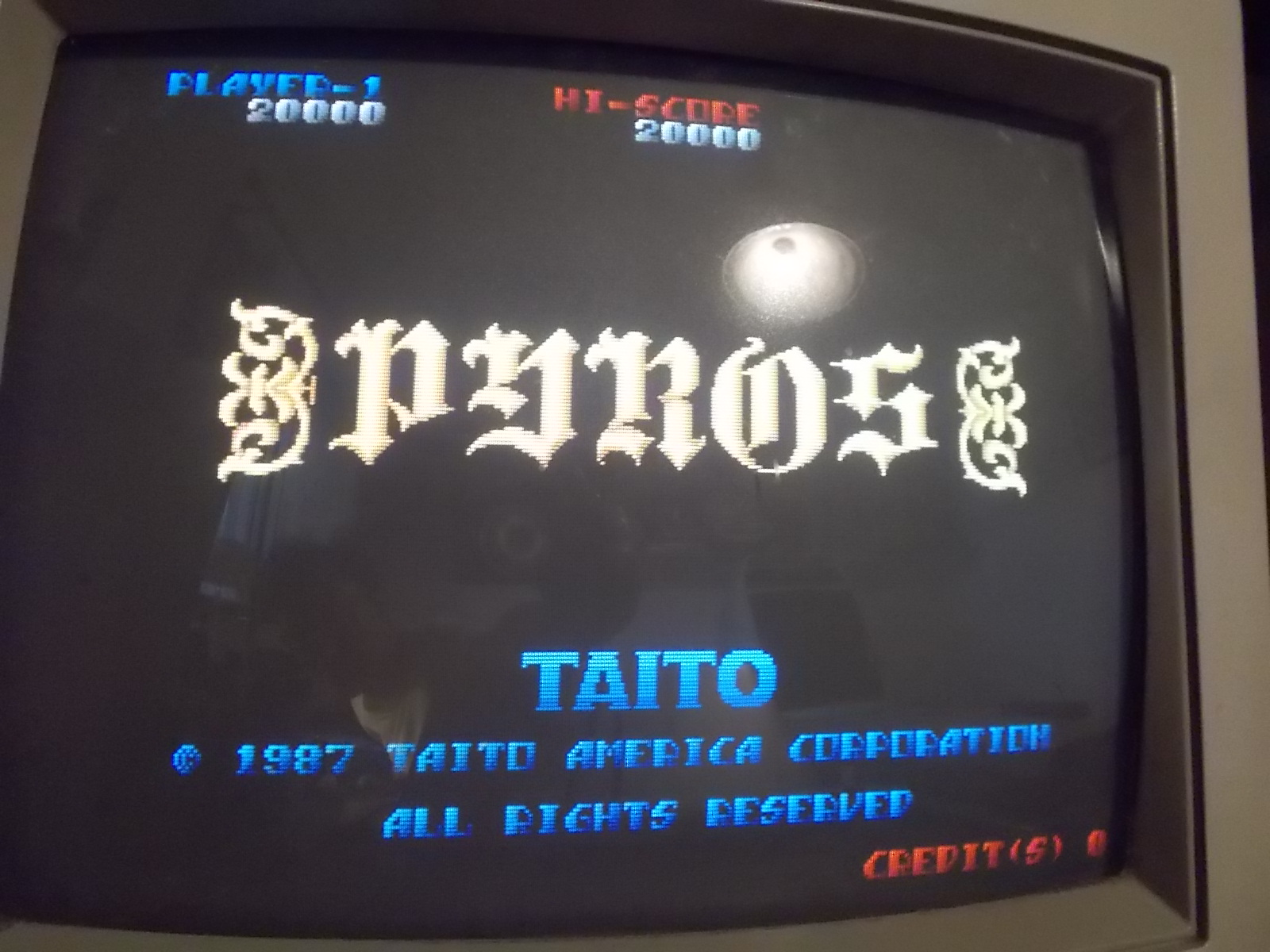
I got this faulty Pyros (US version of Wardner) PCB from Ebay :
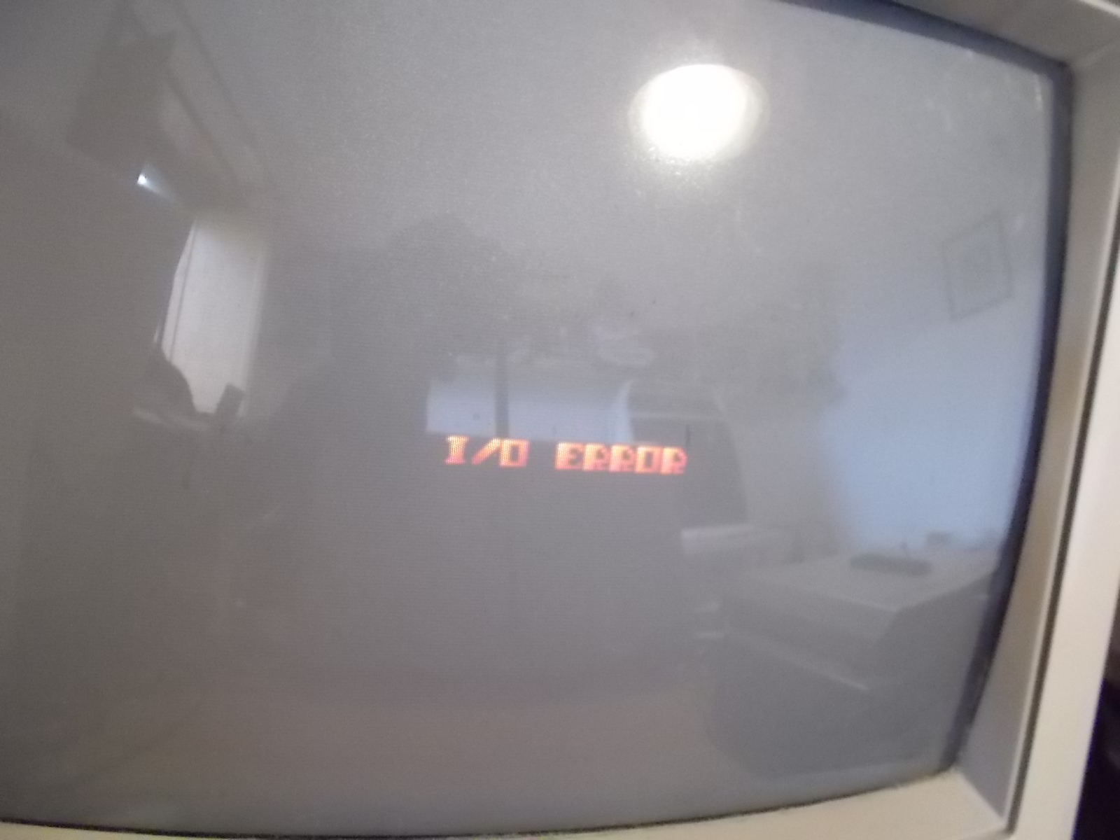
It was not really cheap but it was worth the buy since, on the basis of the seller description, I was confident it could be an easy fix.Board showed an ‘I/O ERROR’ upon boot:
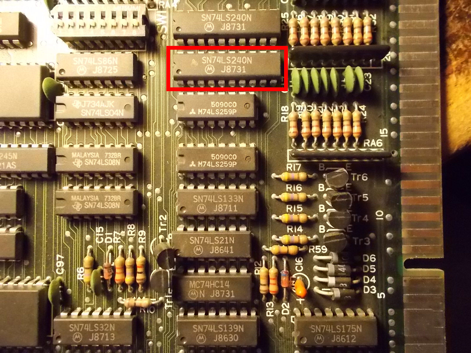
I knew from my experience that this board produces the mentioned error when, indeed, there is some troubles with the inputs during the startup sequence (also a simple buttom pressure would cause it).So for first I went to check with my logic probe all the inputs probing pins on the JAMMA edge connector.All of them were high except the ‘COIN 2’ (pin 16 solder side) which was stuck low.I could trace it back to pin 17 of a 74SL240 @20N :
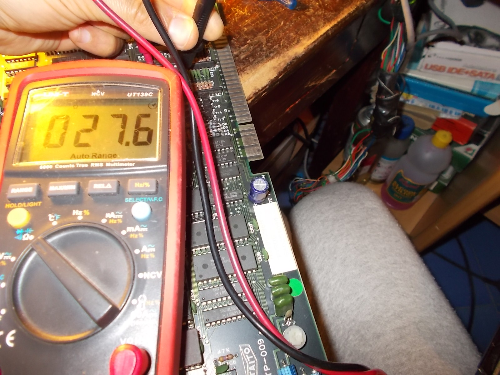
I could measure only few Ohms of resistance between this pin and ground, this meant internal junction was nearly shorted to GND:
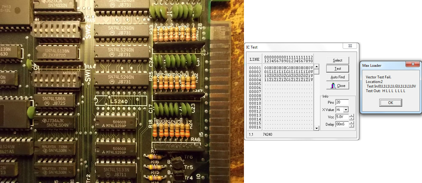
Once desoldered the chip, it obviously failed the test:
With a good chip, the board entered in game with no further issue.
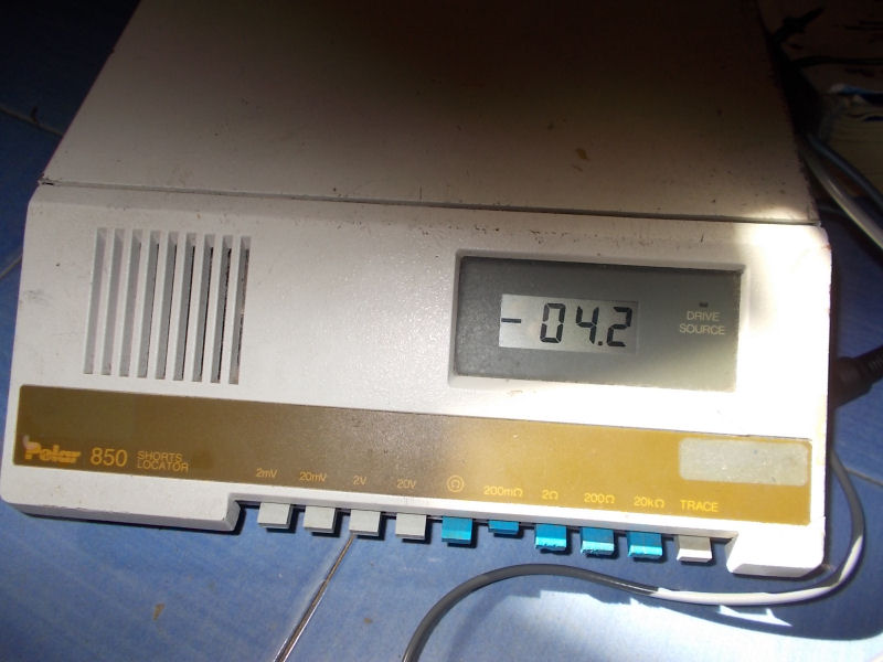
Last week I bought on Ebay an untested Polar Toneohm 850 (picture from Internet) :
For the uninitiated this is a instrument that is able to locate quickly and accurately shorts on PCBs.Device is essentially an audible milliohmmeter which, indeed, produces a tone whose frequency is inversely proportional to the resistance measured across its probes.The more you get closer to the short and so the lower will be the resistance, the higher will be the produced tone.This is very useful when you come across a PCB with a dead short or small resistance between VCC and GND, using a normal multimeter would have no effect since you will end up to measure always same resistance values due its accuracy (most if times of 0.1 ohm ) which is too coarse.
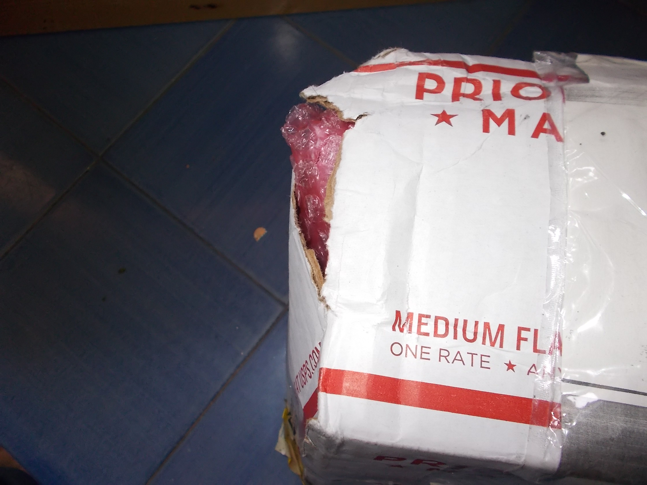
So, I bought this kind of equipment which arrived me a couple of days ago.When I saw the package, I immediately had a bad feeling :
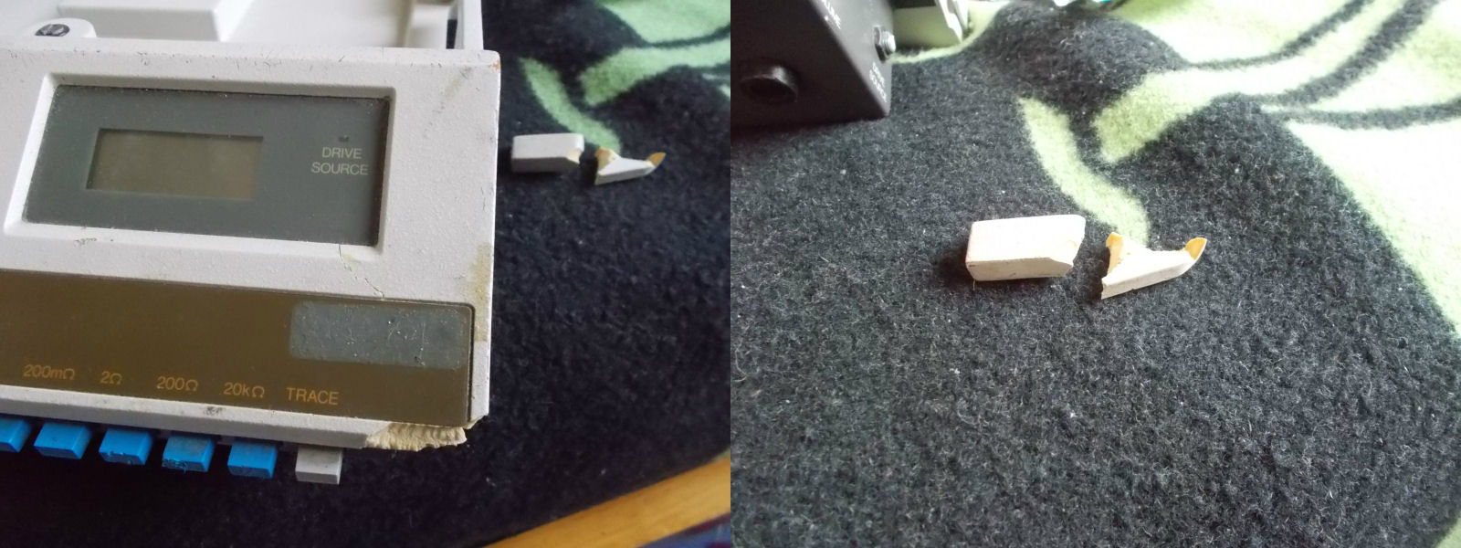
The box was broken and, once opened, the case of the unit too:
But worst , the unit didn’t power on at all, it was competely dead while the seller clearly stated (sending me also a picture) that, although untested, instrument turned on showing numbers on display.
Since I needed this piece of equipment I opted for repairing it instead of asking for a refund and send it back.
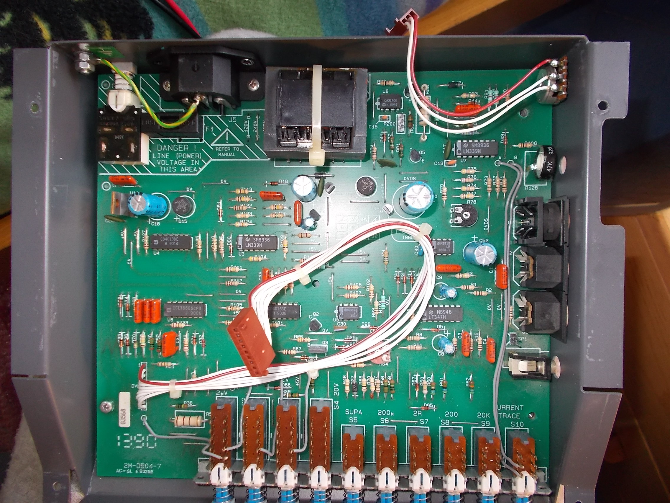
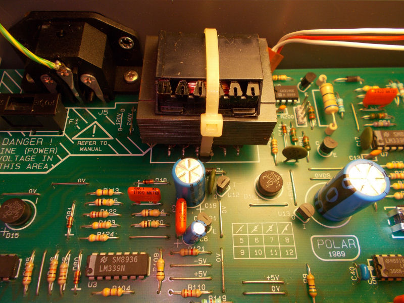
I opened the unit and PCB was in untouched state, no sign of damage or burn components.
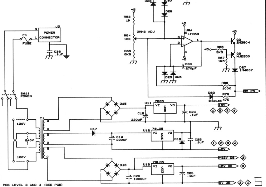
First of all I went to check voltages on the various test points, I could only measure few Millivolts.Thanks to the user ‘Fraser’ (thanks again!) on EEVblog forum I got schematics of this specific model so I could start my troubleshooting more confident.Design of the unit is quite simple : the 220VAC ( unit came with 120VAC line selected so had to change it accordingly to my country) reaches the main transformer ‘T1’ being reduced to 9VAC then it got rectified by a couple of bridges and then regulated by a 7805 and couple of 78L05 providing power for all the logic :
Again, I was able to measure more or less +1V on the inputs of the tree voltage regulators so problem was upstream, specifically in the main transformer (‘T1’ on schematics) :
Said simply, a transformer is a device made of a primary winding and one of more secondary windings.Windings are usually wound around very high permeability ferromagnetic cores.A varying current in the transformer’s primary winding creates a varying magnetic flux in the core which is transferred to the secondary windings by magnetic induction.
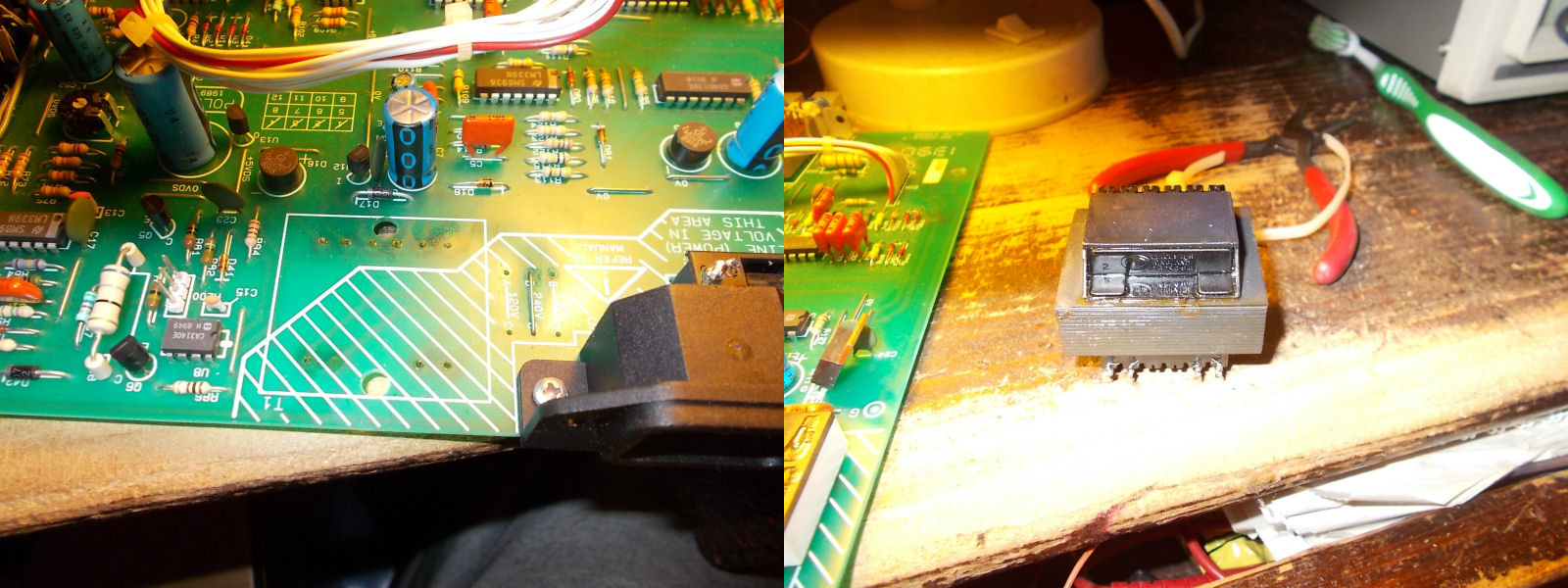
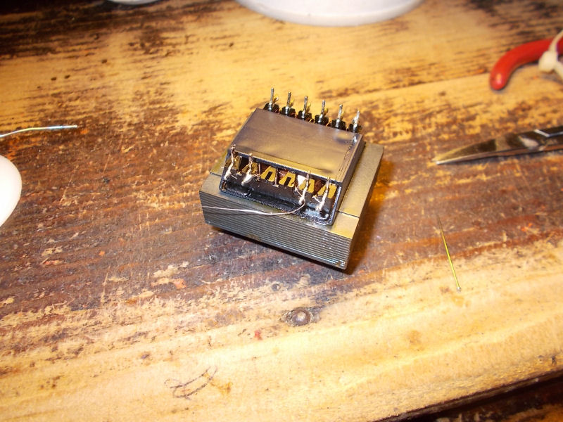
So, my problem was clearly located in the windings.I removed the transformer:
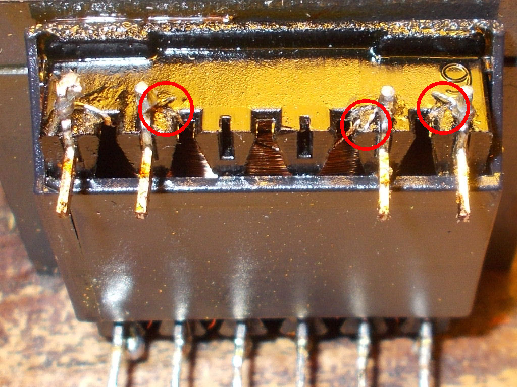
I went to check windings with my multimeter and none of them gave me resistance values, they were almost all opened due the shock received during shipping!But luckily they were interrupted just near the pins, see picture of primary ones for example :
A bit of ‘surgery’ was needed using some AWG30 wire to restore all connections (part in excess of wire was cut, obviously)
Once mounted the transformer and reassembled all the pieces, the unit came back to life fully working!
Video below shows a testing on an arcade board where a 100nF by-pass ceramic capacitor was intentionally shorted:
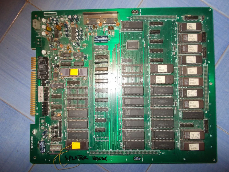
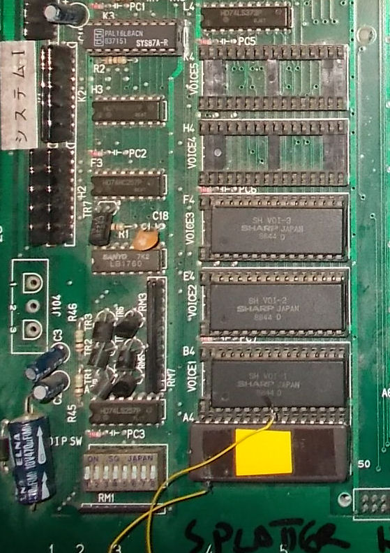
I got from New Zealand this genuine Splatterhouse PCB for a repair:
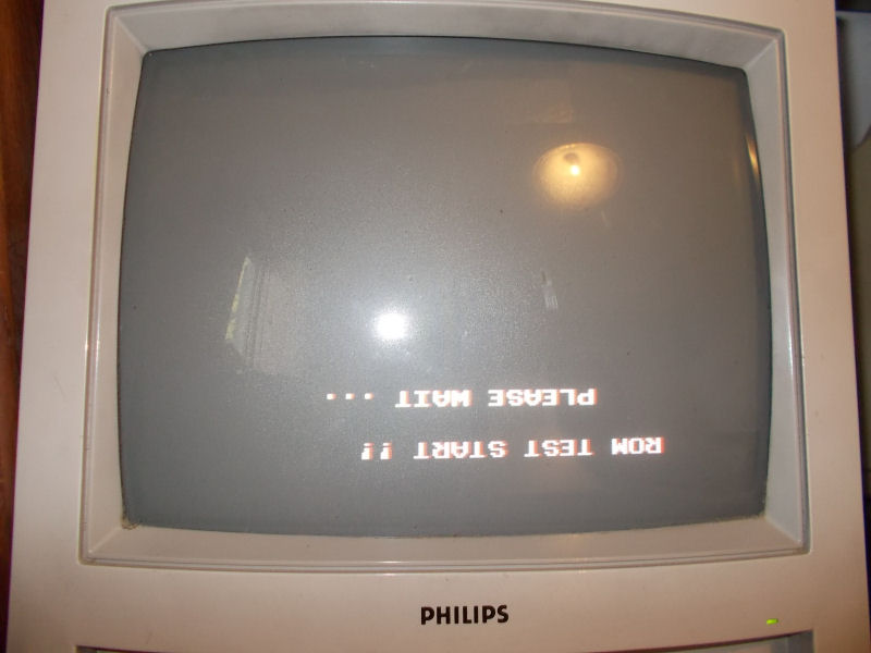
Upon boot the board was stuck on a “ROM TEST START !! PLEASE WAIT…” message displayed upside down :
From my past experience I know for sure this issue is caused by a bad ’64A1′ custom replaceable with a programmed Hitachi HD63701 MCU (plus a patched ‘VOICE0′ ROM in order to handle two custom opcodes of the ’64A1’) following this procedure:
But in this case, as you can see from the above picture of the board, the owner already replaced the ’64A1′ (and at same time patched the ‘VOICE0′ ROMs using an hacked 1Mbit JEDEC EPROM in place of a non-JEDEC one ) and this didn’t fix the issue.For first I reverted the modification the and reinstalled the original custom ’64A1’.With this configuration the board successfully booted into game although some sound samples were bad.This lead me to think that there could be some problem is the data bus of the VOICE ROMs which prevented the HD63701 MCU to correctly read the patched data causing the missing boot. :
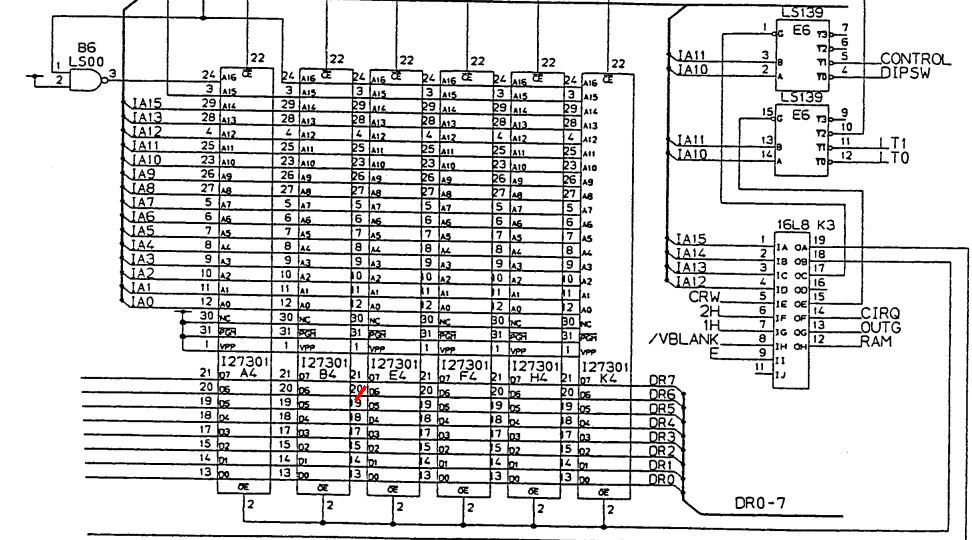
So, assisted by schematics, I went to check the involved circuit and found that pin 20 (data line D6) of the VOICE ROMs (Splatterhouse use only four of them to store samples) was not daisy-chained as it should have been:
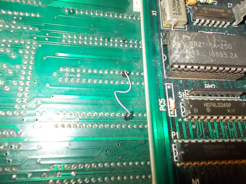
In the above snippet of schematics you can see (red mark) where extactly trace was interrupted.I simply used a bit of AWG30 wire to restore comnection:
This fixed completely the game using both the original ’64A1′ custom and the HD63701 MCU.End of job.
PAL UpdatesComments Off on Irem M72 PAL dumps update
May232016
Our member Corrado Tomaselli sent in dumps of some PALs from Irem M72 boards :
R-Type
Gallop
Dragon Breed
Ninja Spirit
Ninja Spirit dump was already present on database and marked as tested, R-type one was too but untested so this new one will replace it.The other two were undumped.The PLDs are located on ROM board (the top one) and are specific from game to game.
Dumps have been successfully tested on GAL16V8 targeting device.Thanks to Corrado for his contribution.