Caius

Thunder Dragon 2 repair log

 PCB Repair Logs  Comments Off on Thunder Dragon 2 repair log
Dec 242016
 

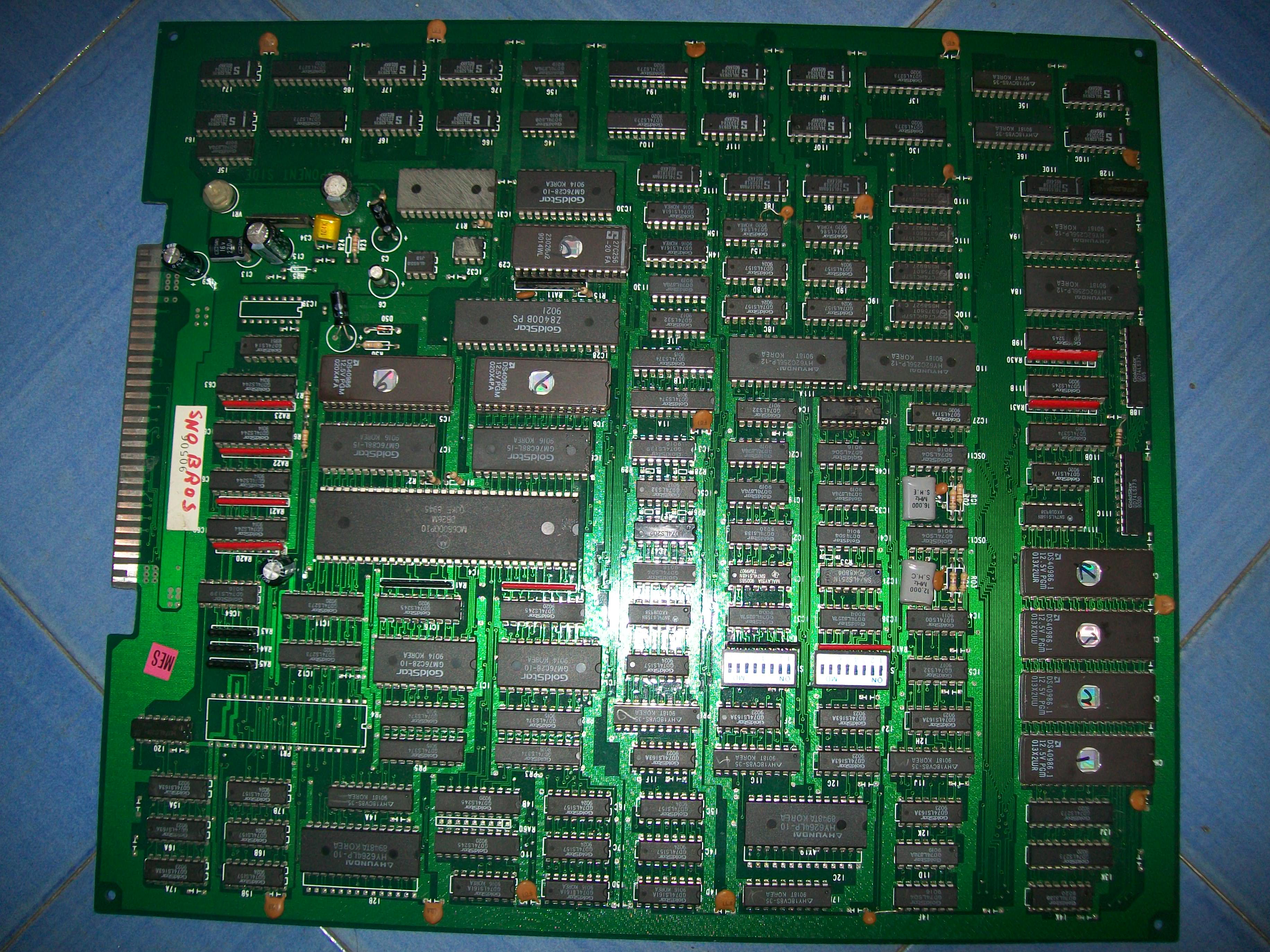
Got this Thunder Dragon 2 for a repair :

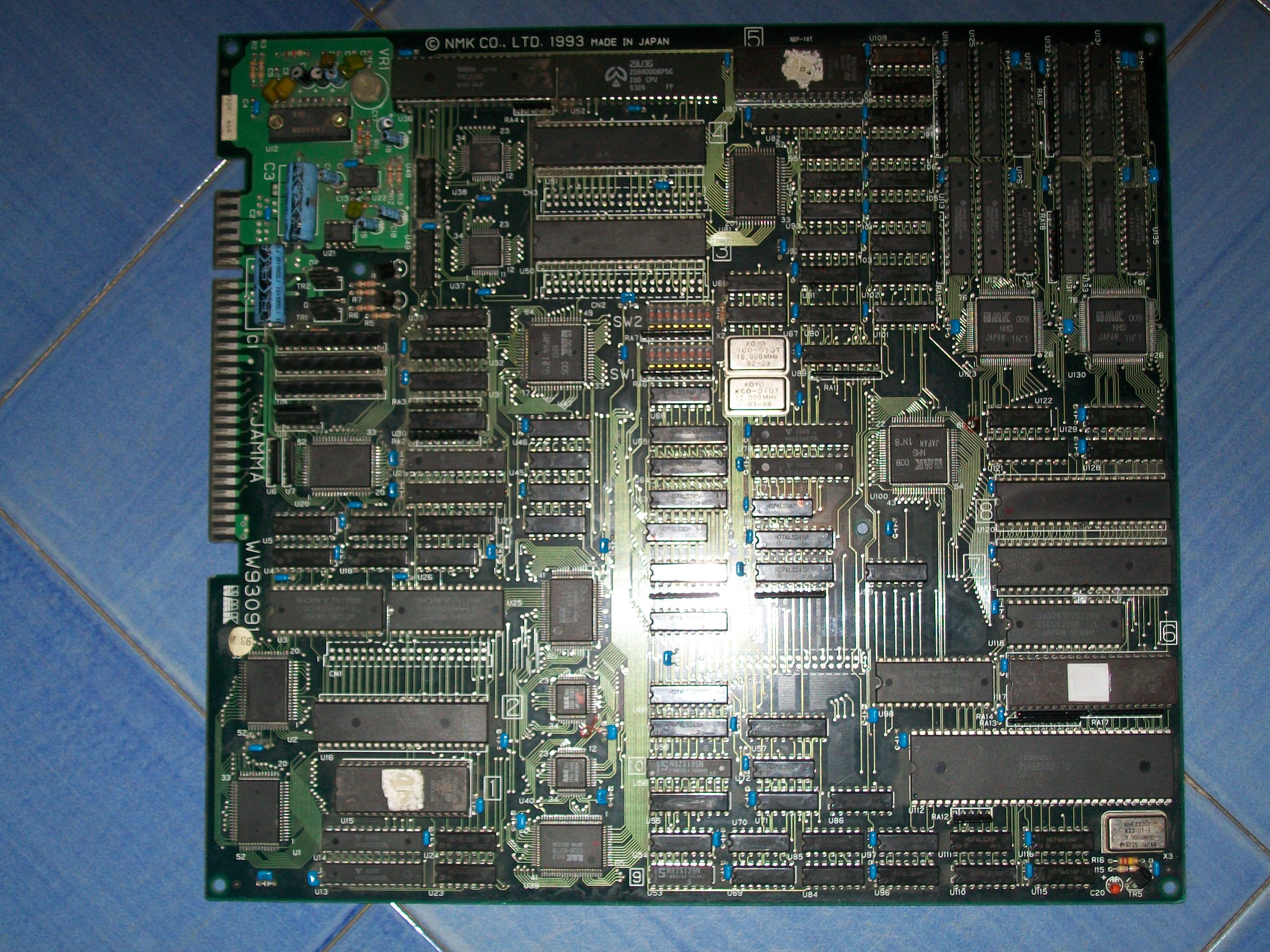
According to the owner, the PCB has suddenly developed a graphic fault, this was confirmed once I powered up the board:

In this close up you can see better the kind of fault:

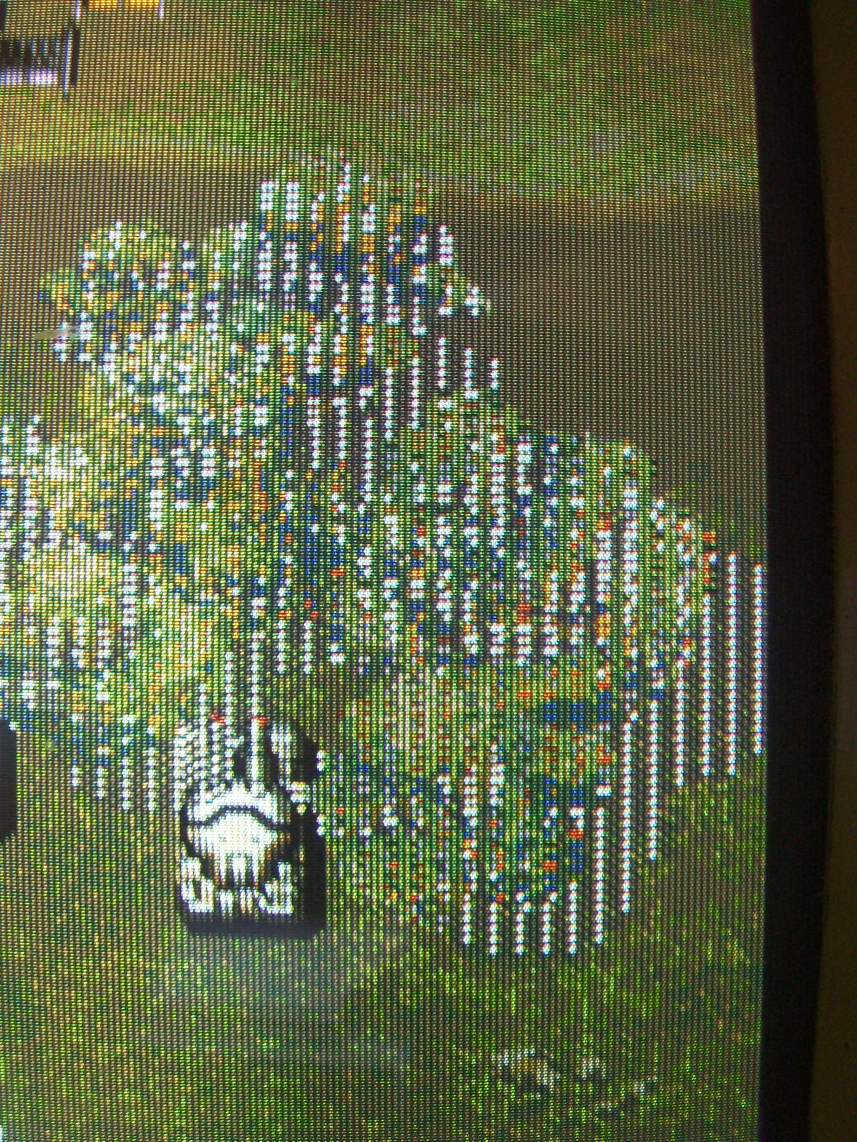
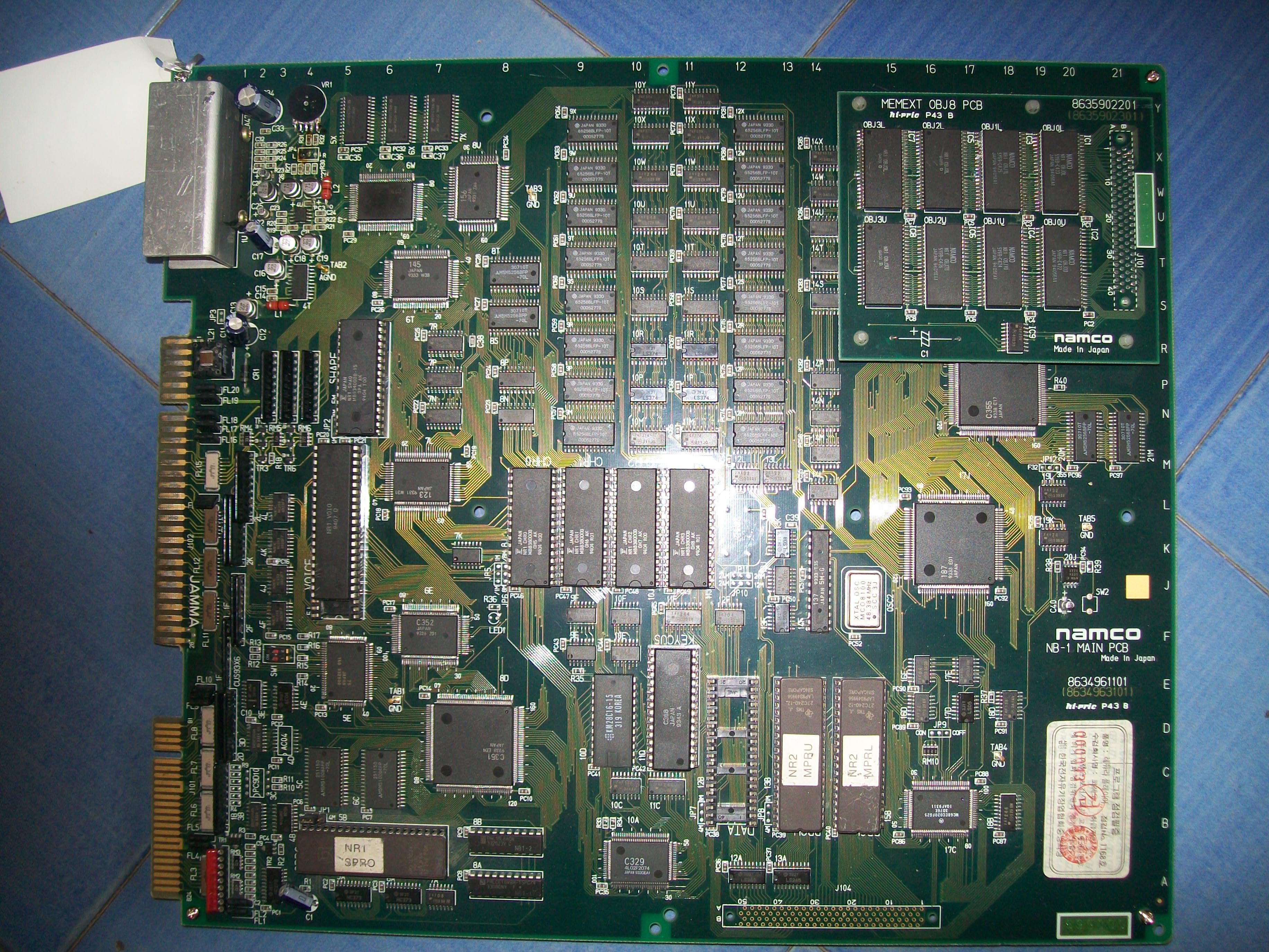
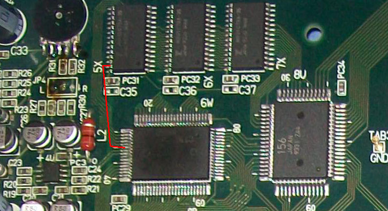
Some part of foregrounds had missing lines and they were flashing (see clouds in the above video to make an idea of).Not being schematics available, I started to study the hardware and found, that shorting some pins of a CXK5164P RAM @U136 (there are four of them) changed the way the fault appeared:

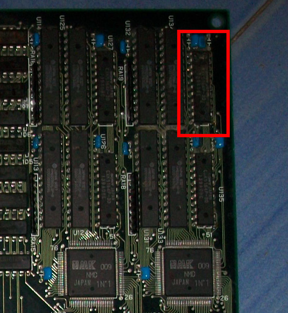
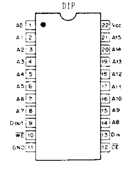
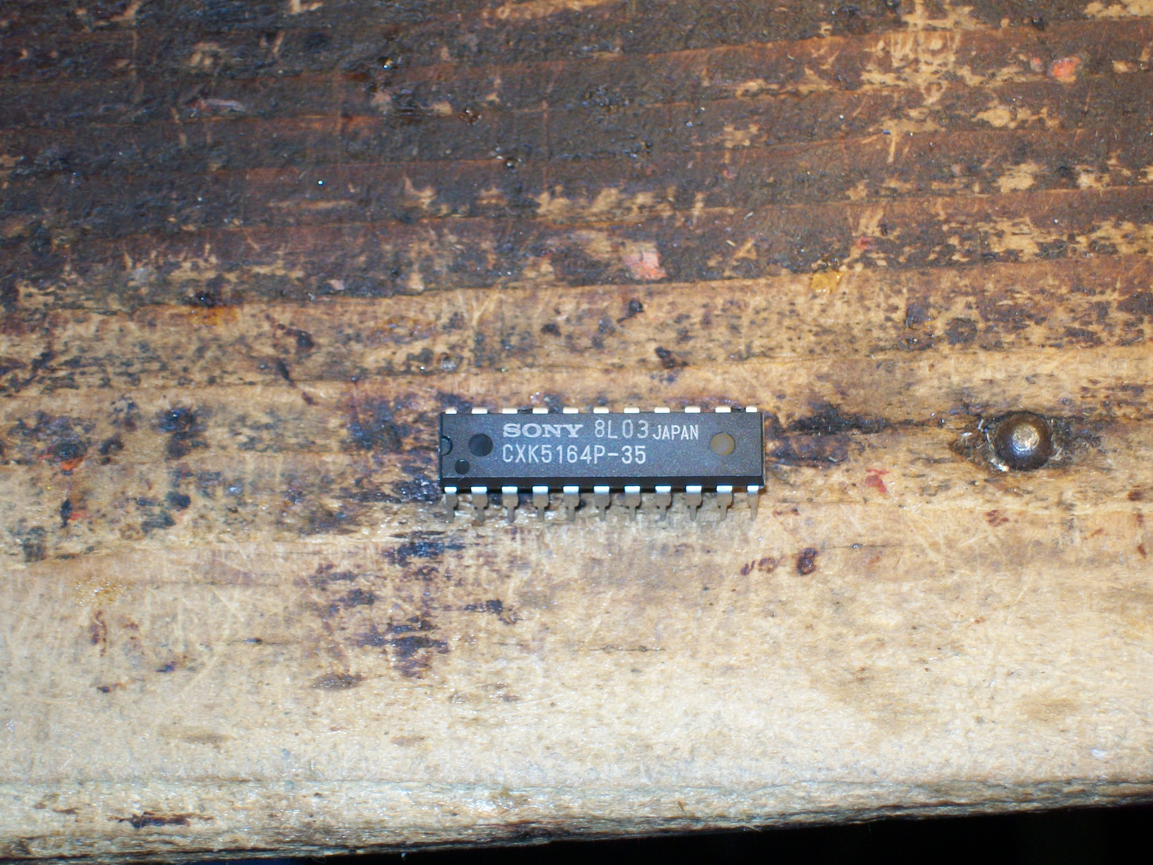
This is an unusual 22 pin static RAM of 64K x 1-bit manufactured by Sony (usually we encounter 1-bit RAM as dynamic ones) but I could find its datasheet and hence pinout:

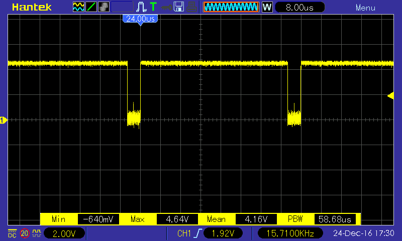
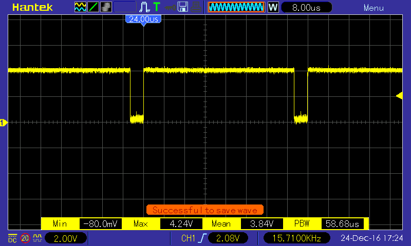
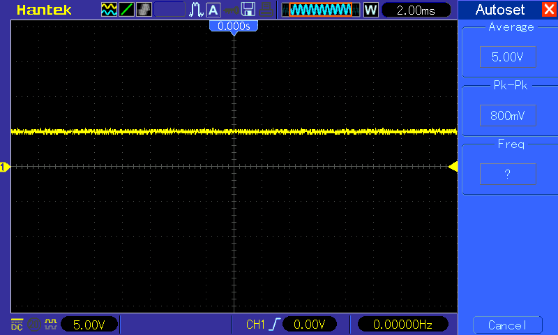
All pins were correctly toggling but analyzing with a scope the DATA OUT (pin 9) I found discrepancies with the same signal from the other three RAMs ( good signal on the left, presumed bad one on the right of the below picture):

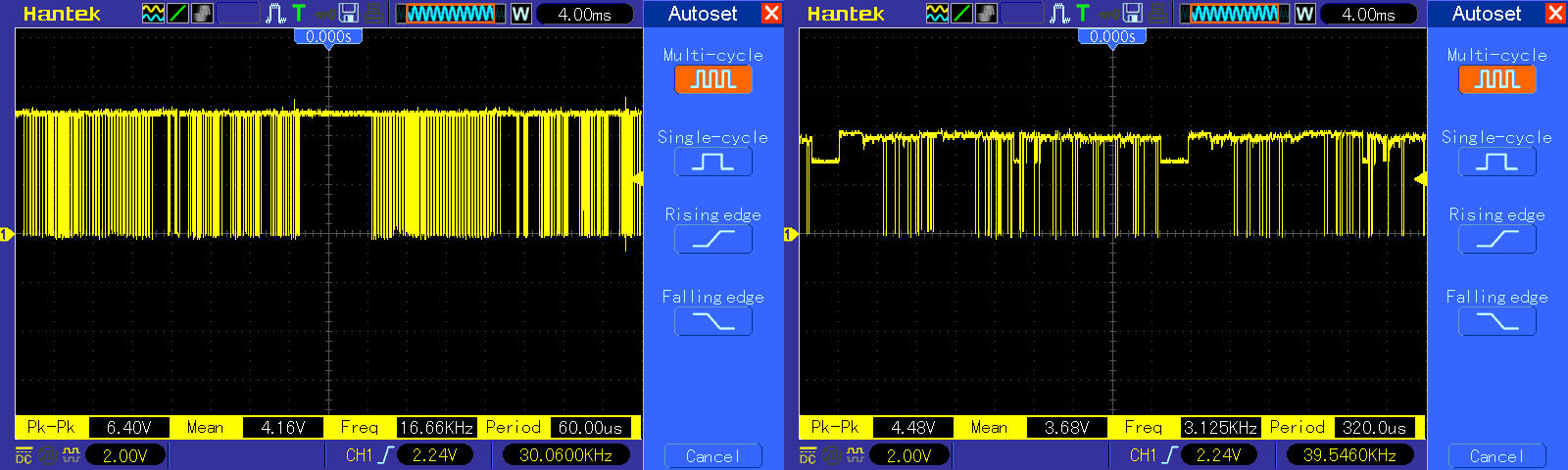
As you can see, transitions of the right waveform are not regular sign of bad data coming out the device.At this point, I had to order a spare since I had no stock of this unusual static RAM.I had to wait almost a month before getting the right part since at first the seller sent me by mistake some OTP EPROMs.But at the end I received it:

And it was worth the wait since I could finally fix this great shoot ’em up!

 Posted by at 6:08 pm

Snow Bros (bootleg) repair log

 PCB Repair Logs  Comments Off on Snow Bros (bootleg) repair log
Dec 242016
 

We all know that a bootleg is a copy of an original board and often a not perfect one since they could be not well engineered.They can suffers from different issues, the one that occurs most often is an unstable video SYNC.Just like this Snow Brows bootleg:

Board played fine but screen was wavy :

Analyzing the SYNC signal with a scope,  amplitude of pulses seemed a little bit over the standard , +4.16V as average while usually they should be within +4V :


This was most likely the reason why my monitor didn’t like it so I thought about a workaround.Usually it’s suggested to use a 5K Ohm potentiometer set as voltage divider : one terminal to the SYNC signal generated by the PCB, the other tied to GROUND and the wiper (the central one) to the  SYNC pin of JAMMA connector.In this way you can adjust the SYNC signal voltage between the original voltage level and GROUND.I wired the potentiometer in this way and installed it on the JAMMA connector of my supergun.Adjusting it, I got a stable screen but I wanted a permanent solution on the PCB.So I used two resistors as a voltage divider:

In my case I used a 270 Ohm resistor as R1 and a 4.7K Ohm as R2 since, doing a bit of calculation, this should have been enough to bring the signal within standard : 3.93V=4.16V*4700/(270+4700).

I installed the voltagev divider on the solderside of PCB (obviously I first cut the trace going to PIN 13) .

This was what I measured:


My monitor was finally happy with it.End of job.

 Posted by at 3:53 pm

Daimakaimura (B-BOARD ‘88622B-2’) PAL dump added

 PAL Updates  Comments Off on Daimakaimura (B-BOARD ‘88622B-2’) PAL dump added
Dec 212016
 

Today we have the PAL dump from a Daimakaimura (Japanese version of Ghouls ‘n Ghosts on a CPS1 B-BOARD ‘88622B-2’ ) thanks to Silvio Grazini who sent the binary dump obtained with the Charles MacDonald 27C020 PAL adapter.I took care of reversing equations onto a GAL16V8 and Silvio successfully tested it on his board.Thanks again to him.

 Posted by at 7:38 pm

NebulasRay repair log #2

 PCB Repair Logs  Comments Off on NebulasRay repair log #2
Dec 152016
 

Got this genuine NebulasRay for a repair:

Game played fine but suffered from a color issue, screen was all yellowish, self-test on boot reported a problem on palette RAMs:

A yellowish screen means that problem is in the BLUE color generation so I started to study the hardware and figured out the RGB circuit:

As you can see from the above picture, there are three 8K x 8 bit static RAMs, each one for a each color.These SRAMs are addressed by the custom ‘156’, their data go to the custom ‘116’ which processes them and generates the different color shades.These digital signals are converted to analog and formed into a single color by three 1K Ohm resistor arrays.Lastly each is color is amplified by a PNP transistor and routed on JAMMA edge pins.

With this knowledge for first I checked the 6264 SRAM @5X (which does the BLUE color), it showed normal activity on data/address bus until I probed its pin 27 (/WE) , it was not toggling like in other two RAMs but it was stuck HIGH so RAM was never written:

/WE signal of this RAM (like the other two ones) are generated by the custom ‘116’:

But with my multimeter I found no continuity, at a closer look the pad of pin 27 of this RAM lost contact with the trace.I promptly restored it and this gave me a fully working board again.End of job.

 Posted by at 9:38 pm

Taito F3 (PCB version) PAL update

 PAL Updates  Comments Off on Taito F3 (PCB version) PAL update
Dec 152016
 

In the past days I got two working Taito F3 boards (PCB version) : Grid Seeker and Super Cup Finals).So I could test the dumps we had from Arabian Magic (thanks to ‘luiskiko’).Some dumps were from PALCE devices so I could successfully test them on GAL without any conversion, the remaining where from PAL devices so I first converted them in GAL format.PAL location and marking are the same between Arabian Magic and Grid Seeker since boards have same layout while Super Cup Finals has a slighty different one but it shares all the PALs (at different location) except for one which is unique and one with different label but same contents.

 Posted by at 7:56 pm