Caius

Kaneko ‘MC-1091/MC-8282’ reproduction

 Reproductions  Comments Off on Kaneko ‘MC-1091/MC-8282’ reproduction
Jan 082018
 

This is another little reproduction project that arose during my repairs.

Some time ago I came across an Heavy Unit PCB which played fine except for the inputs that were not working.This had an explanation:
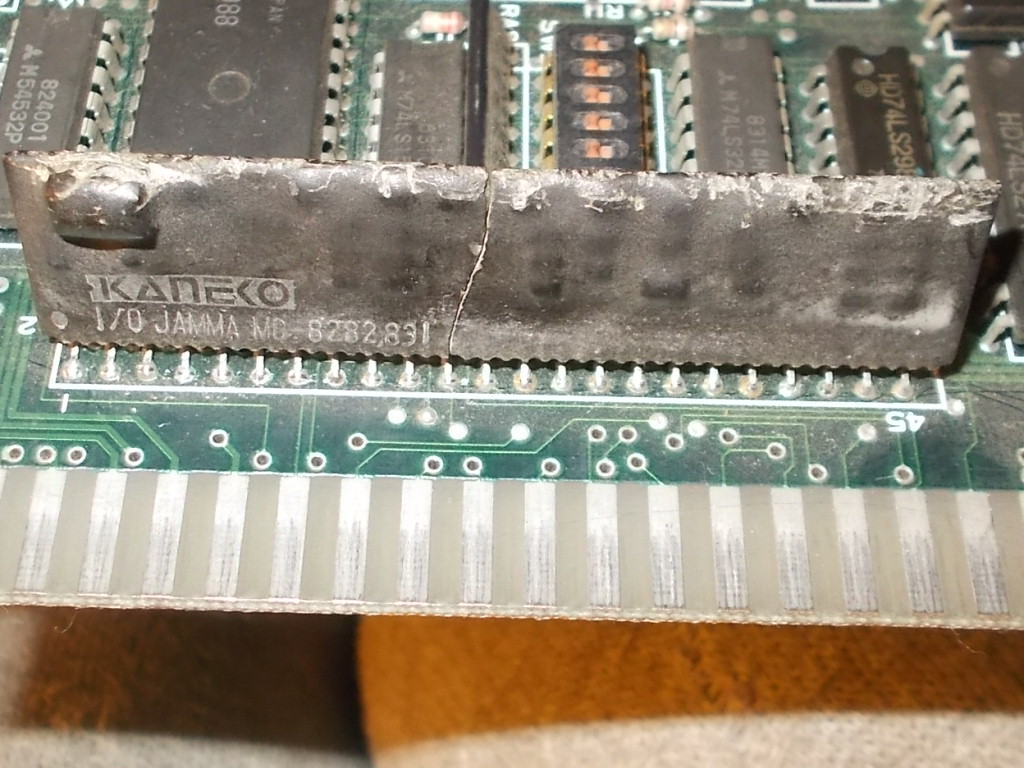
This SIL custom (in ZIP46 package) marked ‘MC-8282’ was broken in half.Like the silkscreening tells (I/O), this custom handles all the inputs.I looked into my spares and found some Kaneko boards that used a similar custom with same number of pins but marked ‘MC-1091’ instead :
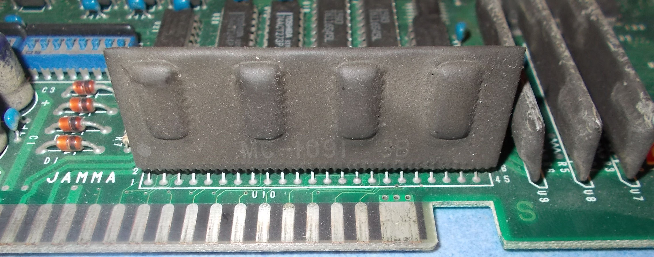
I tried it in my board and all inputs were working again so I came to the conclusion that the ‘MC-8282’ and the ‘MC-1091’ are essentially the same.Not happy enough, I  decided to try to reproduce it.As always in this case, I first ‘stripped off’ the component by removing its coating and did some hi-res scans: 

As you can see from above picture, the designers pratically embedded in a single component a typical inputs circuit that can be found on many arcade boards.Techinically we can think of this custom like a big multiplexer made of four 74SL253 TTLs which receive on their inputs the signals from JAMMA edge connector.Obviously there is a common output enable signal and two selection ones as well.All other parts are printed film resistors (the black squares, the tiny ones are for pull-up), ceramic capacitors (for by-pass and signal filtering) and a couple of SOT-23 parts (involved in P1 and P2 coin input) which I was able to identify as dual diodes  common cathode  :
I fired up my multimeter in continuity check and in some time figured out the design so I made some rough prototyping on a breadboard:
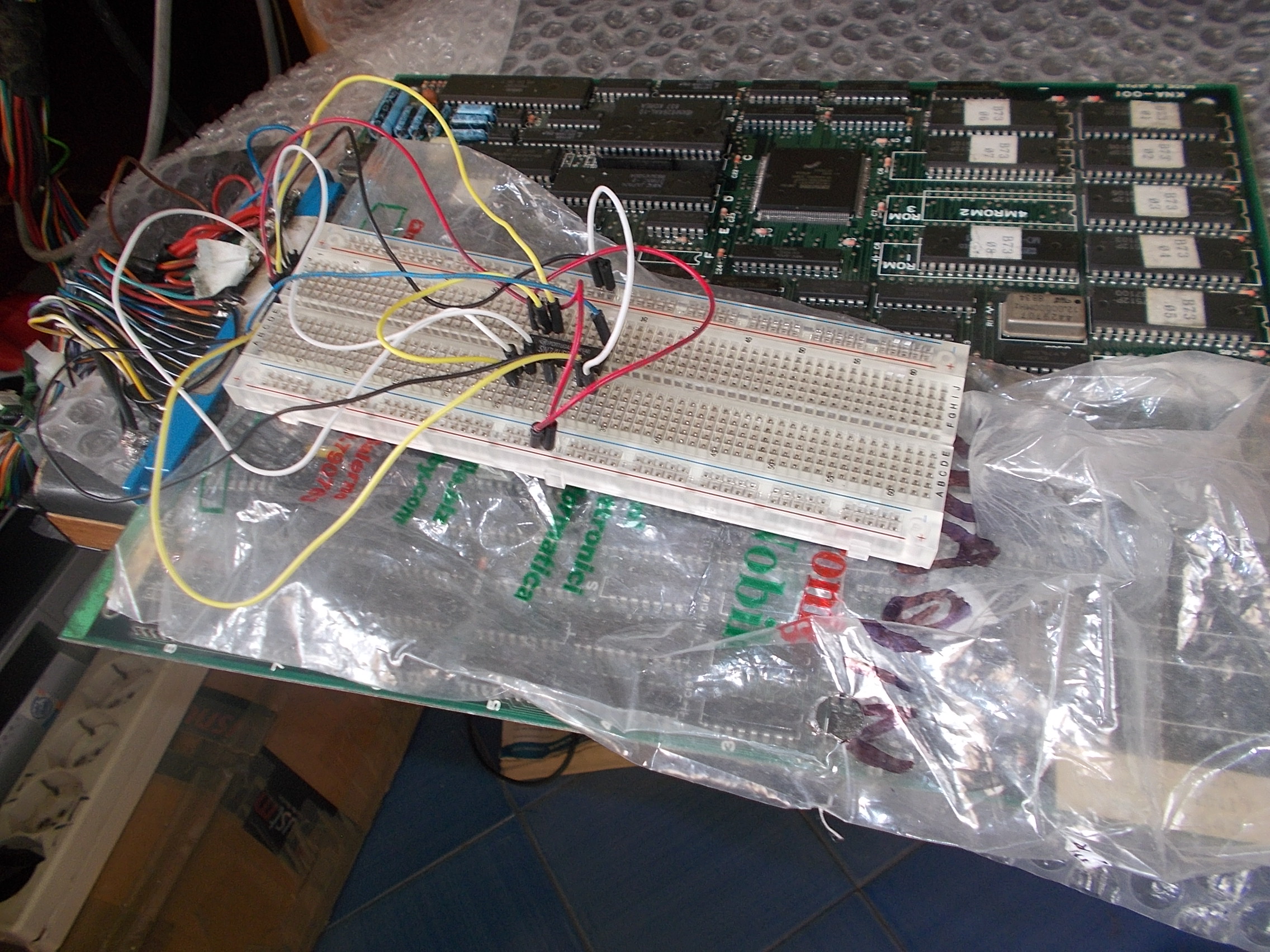
I had success so I start to draw schematics.I intentionally omitted some not vital parts (like the many ceramic capacitors) and used SMD resistors arrays, this allowed me to save room on PCB layout and keep the same dimensions as the original part.I sent the design to manufacturer and received the bare PCBs after some weeks:
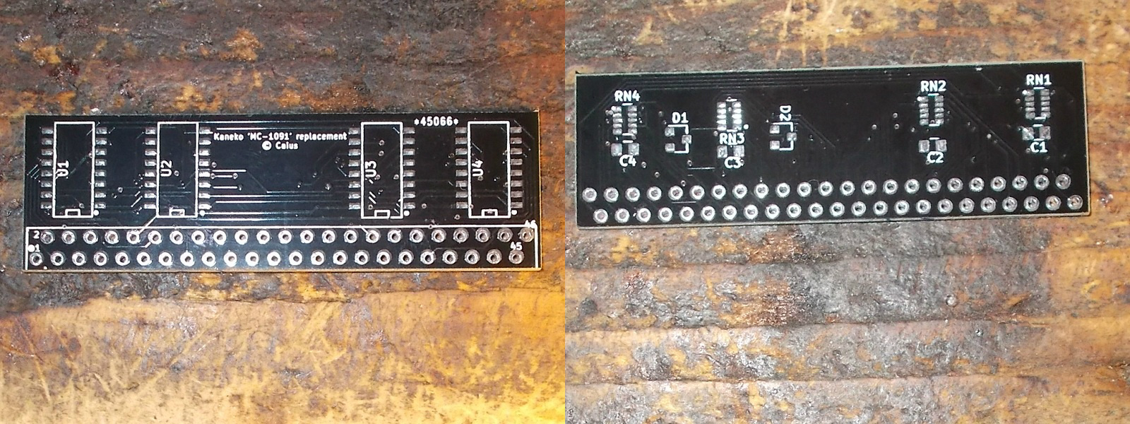
I assembled a unit:
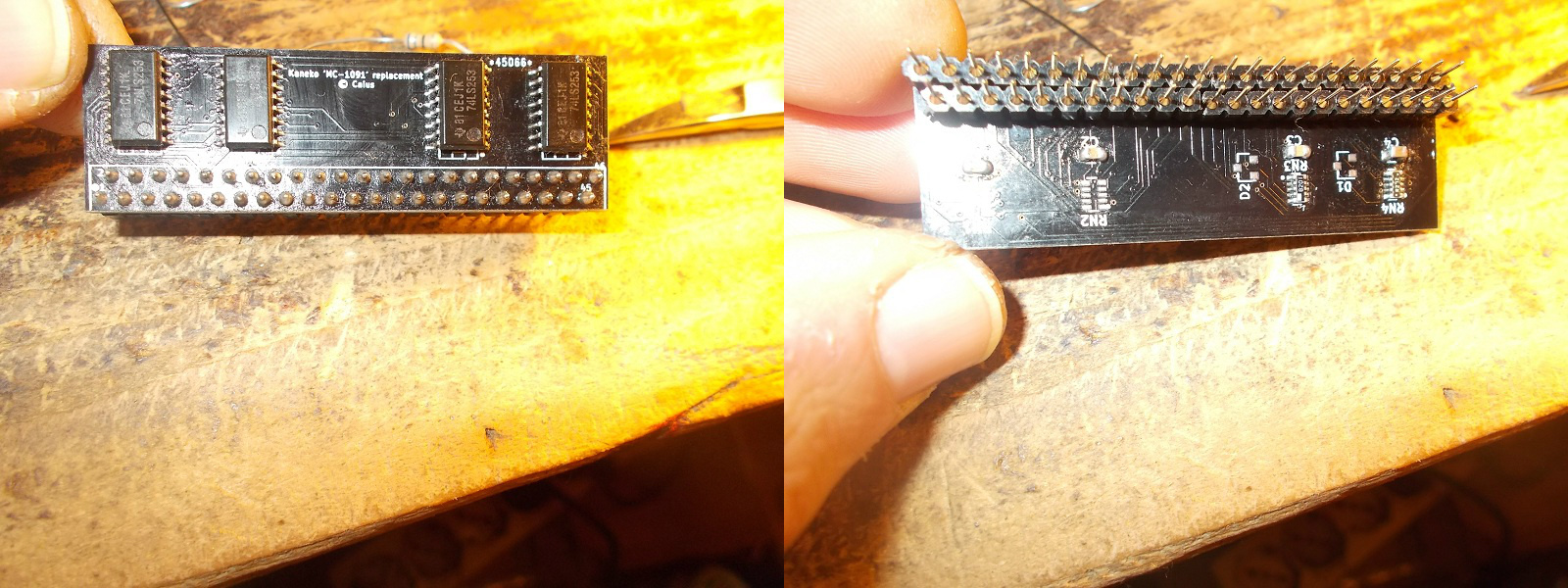
and installed it on PCB:
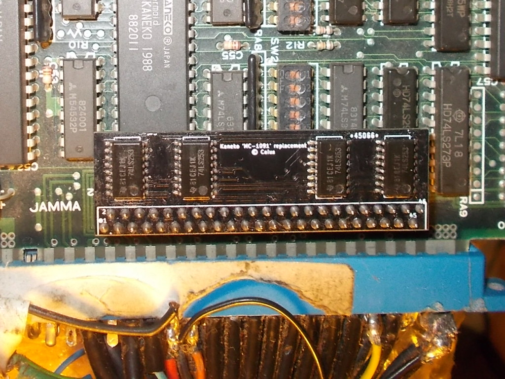
Testing was successful, all the inputs of both players (plus SERVICE ) were correctly mapped and working:

For reference the MC-1091/MC-8282 custom can be found on these Kaneko/Taito/Toaplan PCBs (list can’t be incomplete so other additions are welcome) 

  • The Berlin Wall
  • Magical Crystals 
  • Bakuretsu Breaker 
  • Blaze On 
  • Shogun Warriors 
  • B.Rap Boys 
  • Great 1000 Miles Rally 
  • Bonk’s Adventure 
  • Blood Warrior 
  • Jackie Chan
  • DJ Boy
  • Gals Panic 1, 2, 3
  • Air Buster
  • Snow Bros
  • Heavy Unit

See you all to my next reproduction project!

 Posted by at 9:13 pm

Vulcan Venture repair log #2

 PCB Repair Logs  Comments Off on Vulcan Venture repair log #2
Jan 082018
 

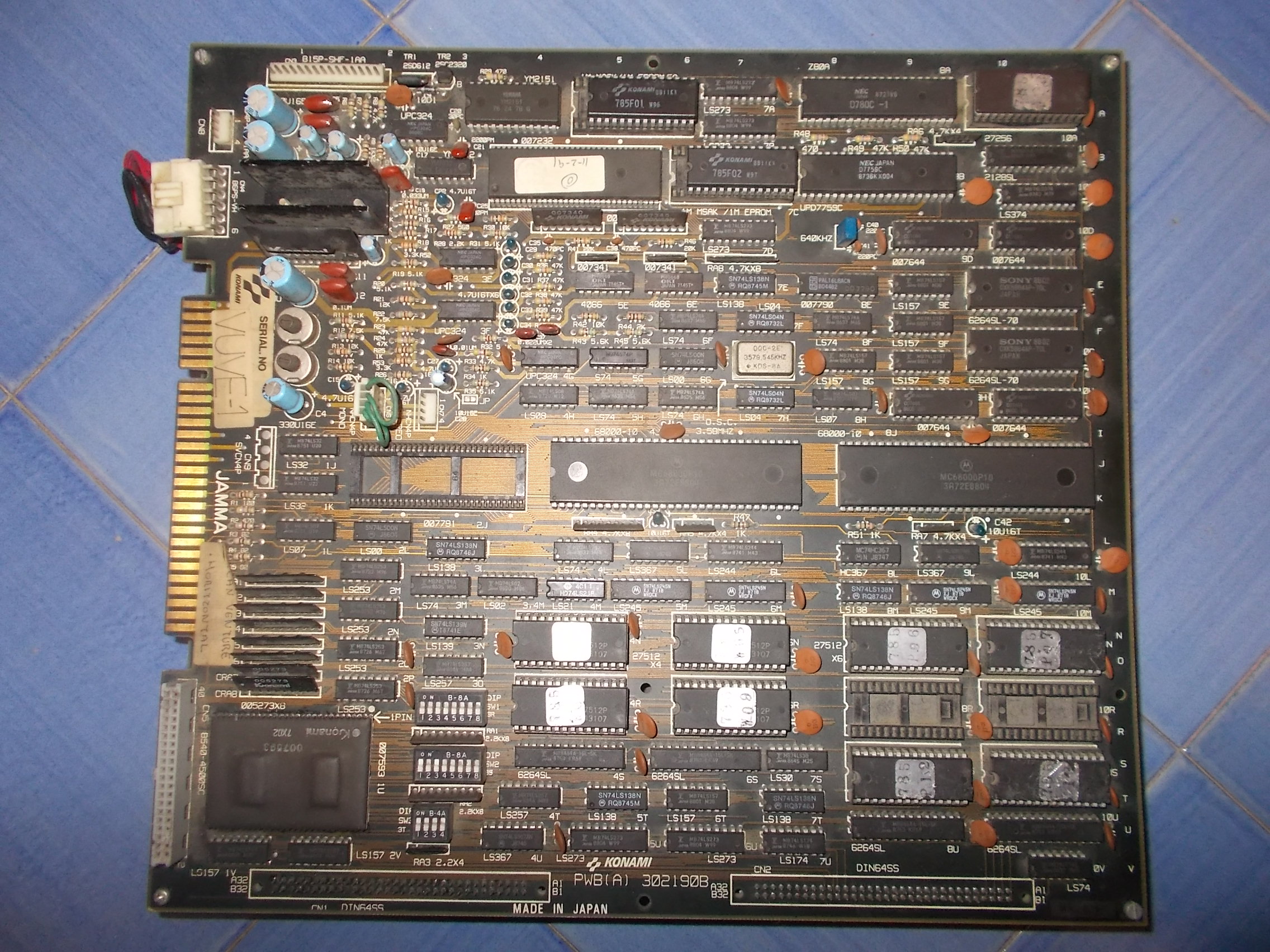
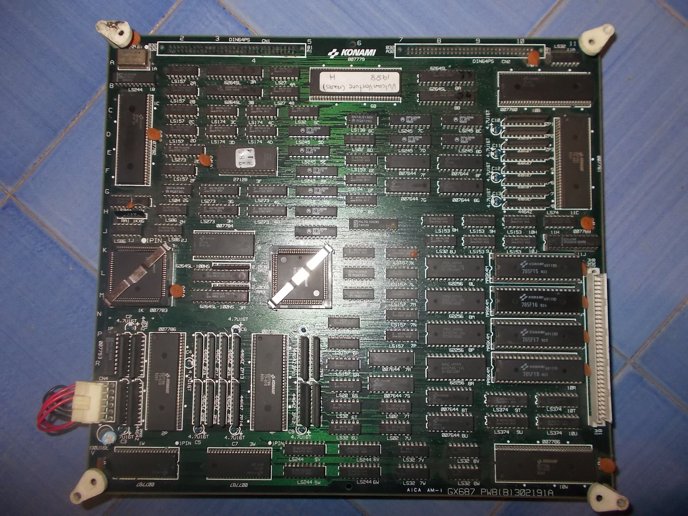
Received from Spain this faulty Vulcan Venture PCB (export release of Gradius II on the glorious’ Konami Twin16 hardware) 

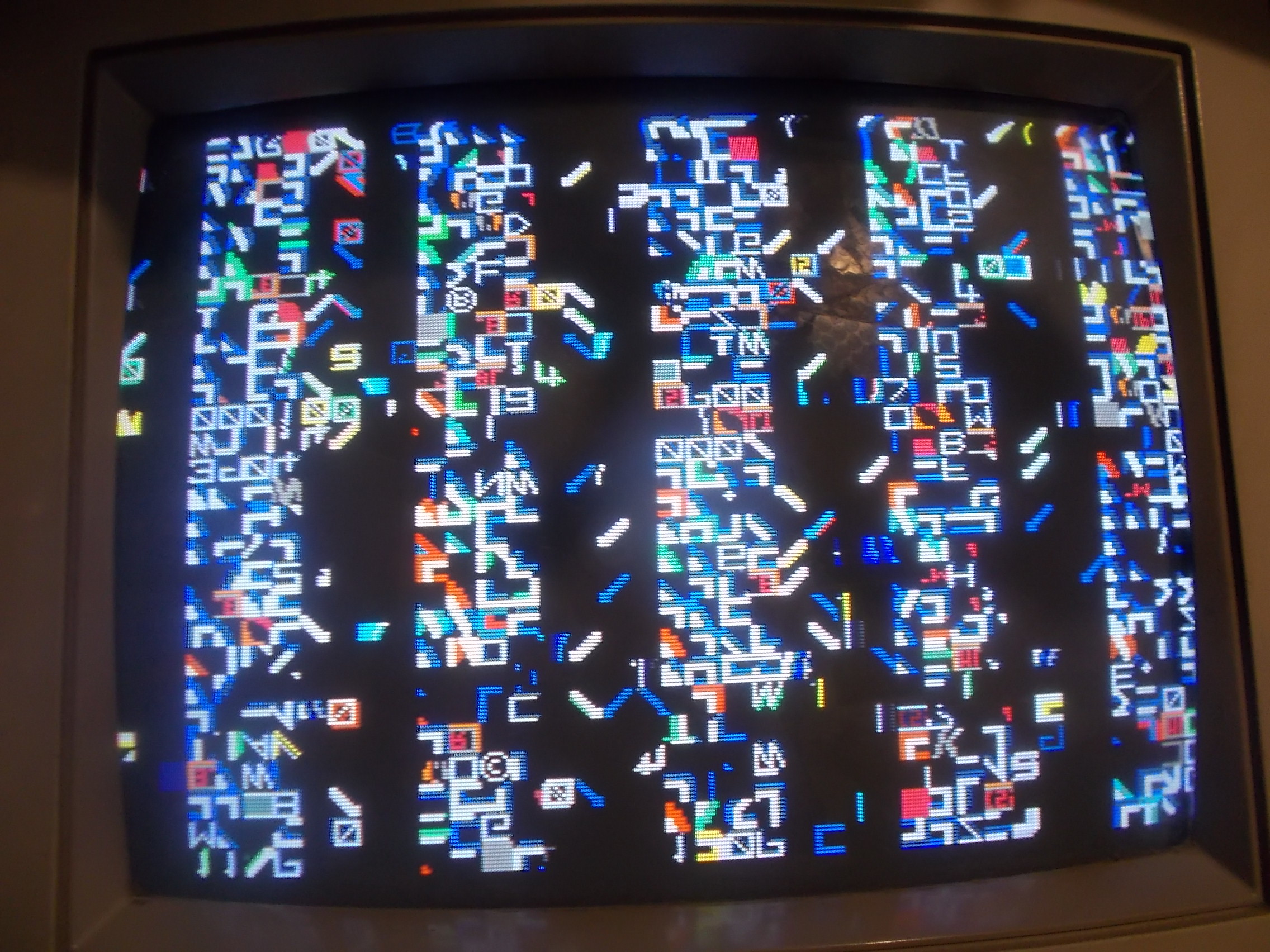
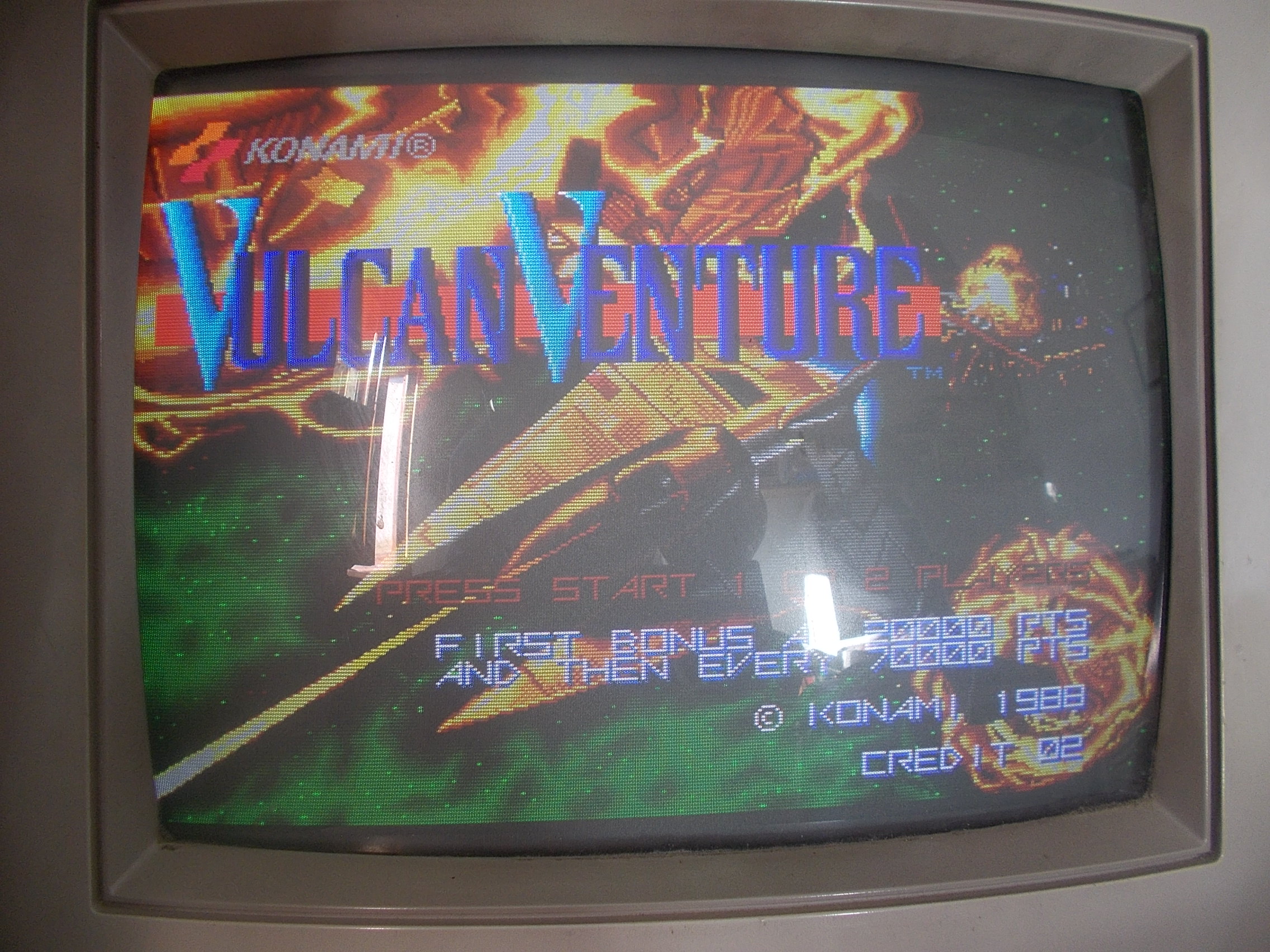
This is what I got once powered it up:

Graphics were all corrupted, you could barely recognize the self-test procedure which failed all the time causing the reset of the whole system in an endless loop.I focused my troubleshooting on VIDEO board:

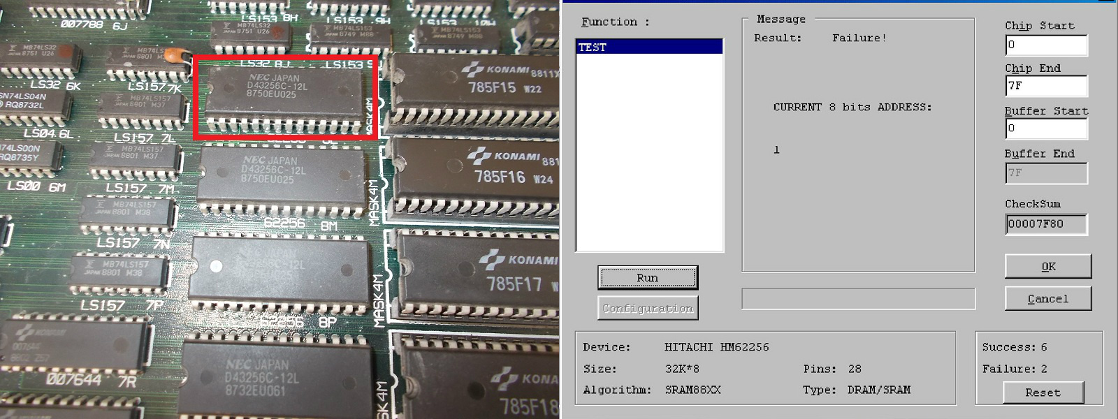
Like the CPU board, also the VIDEO one was almost fully populated with Fujitsu TTLs  but before going thru them I started to probe the various RAMs.I found one 62256 @8L with dead outputs:

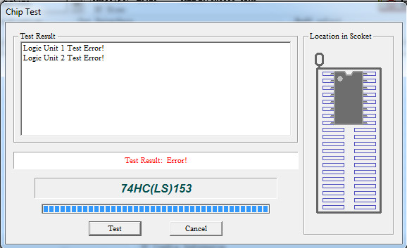
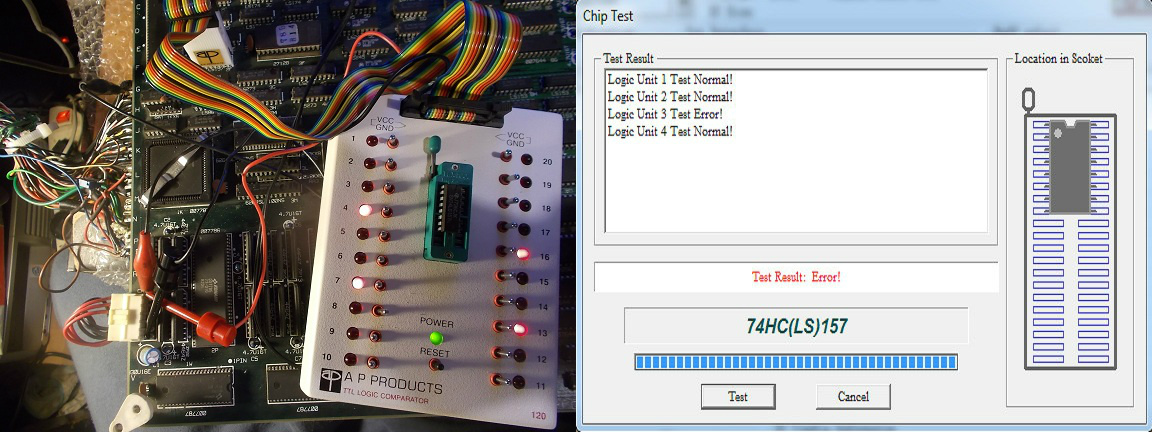
This finding lead to no improvement.So I fired up my logic comparators and started to probe TTLs.Sequentially I was able to locate these faulty ones, all of them on VIDEO board and from Fuitsu:

  • 74LS153 @9H


  • 74LS157 @2F


  • 74LS244 @5W

But the board was still not booting :

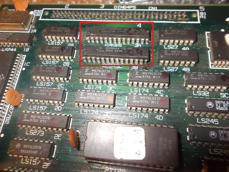
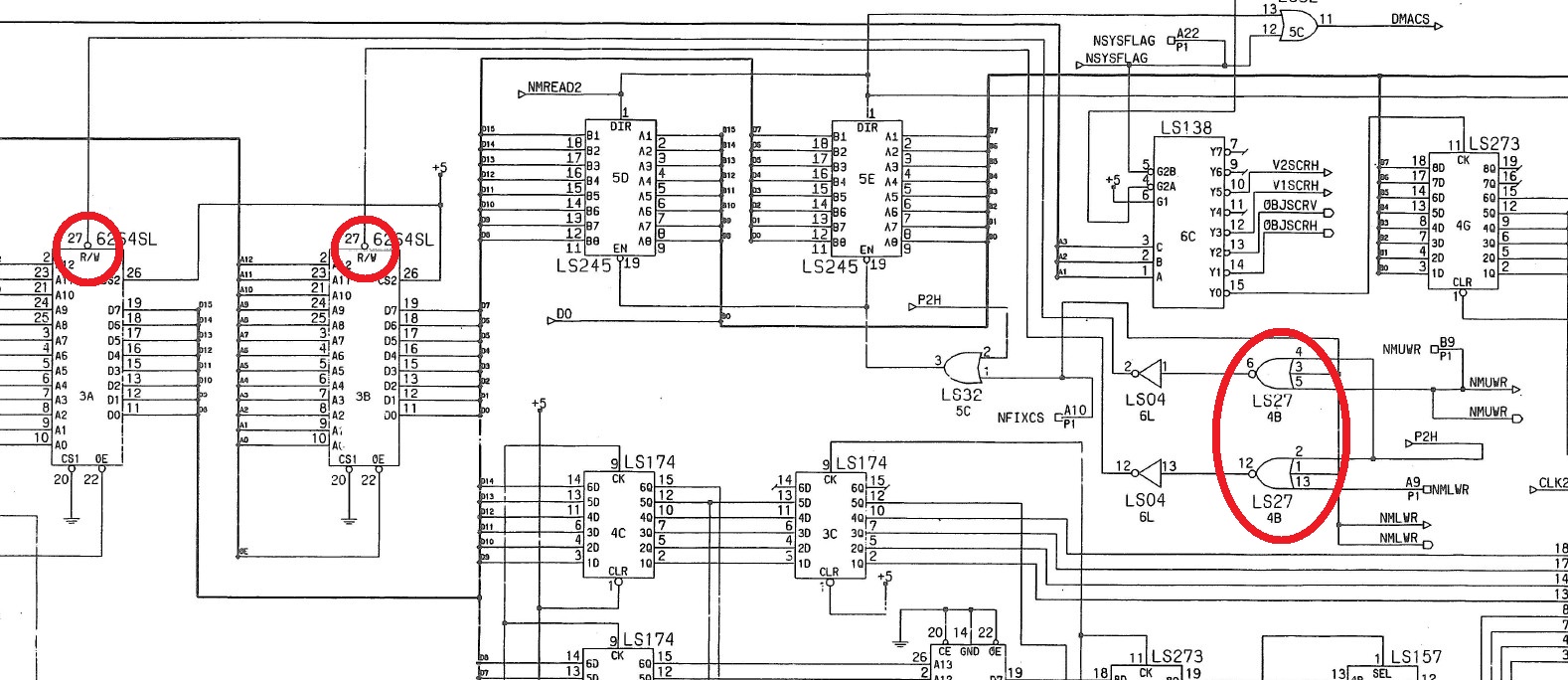
Shorting some data/address lines of two 6264 SRAMs @3A and 3B changed the garbage on screen so this was the path to follow, the problem was in the tilemap generation circuit which these RAMs are part of :

Probing the RAMs revealed that the R/W lines (pin 27) of both were stuck high, according to schematics these signals come from a 74LS27 @4B:


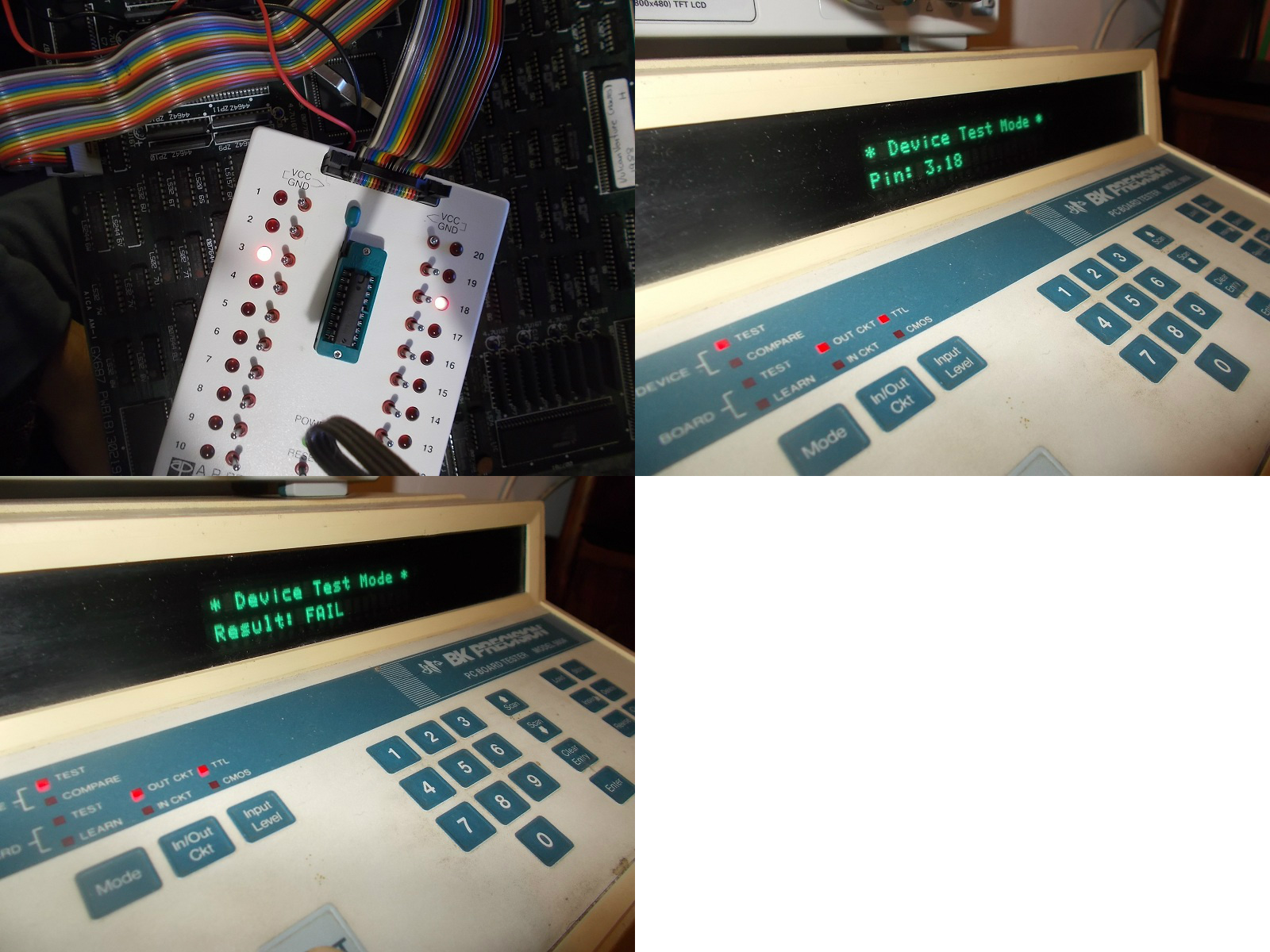
My HP10529A logic comparator confirmed troubles on two outputs of this 74LS27 which failed when tested out-of-circuit:

Now board succesfully passed the self-test and entered in game fully playable with sound but all graphics had very noticeale jailbars:

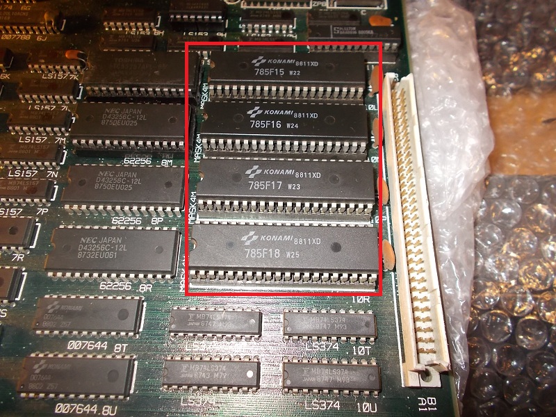
Most of graphics data is stored in four 4Mbit MASK ROMs:

While dumping them my programmer reported troubles for the ones @10L and 10M:


Replaced them with two 27C400 EPROMs fixed the issue and board completely.

Evil Konami (and Fujitsu) defeated again but war is not over.See you to next battle…

 Posted by at 5:56 pm

Dragon Breed repair log

 PCB Repair Logs  Comments Off on Dragon Breed repair log
Jan 052018
 

Received today from Germany some faulty PCBs for repair, there was this Dragon Breed boardset (on Irem M72 hardware)

Sprites were glitched with jailbars thru them:

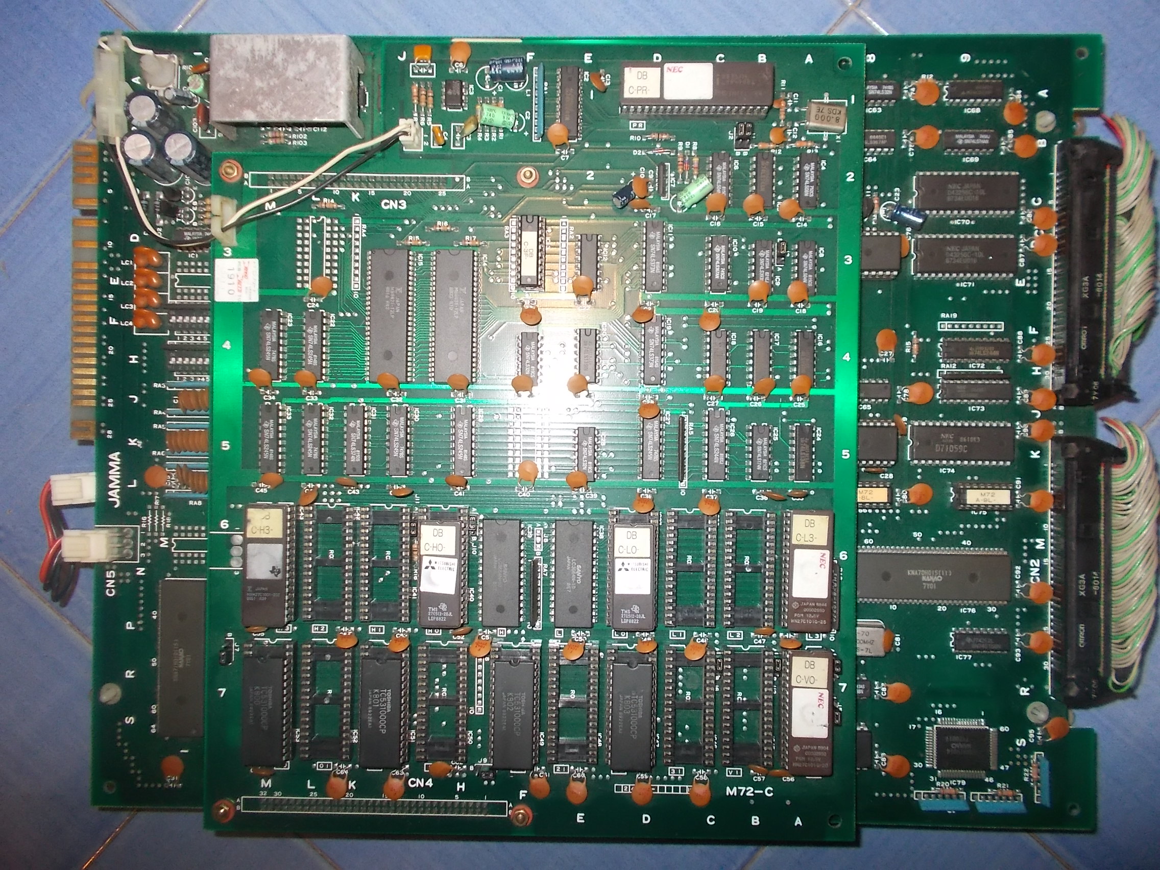
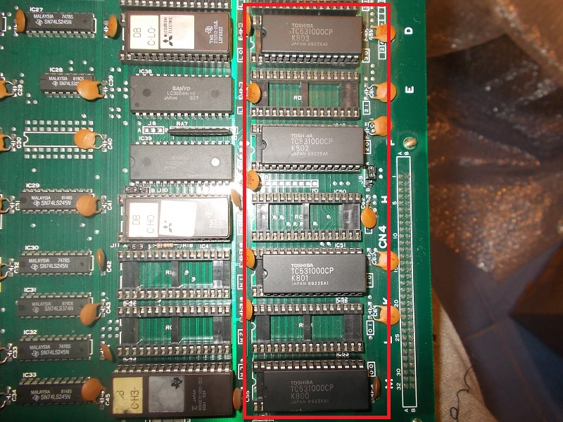
Sprites data are stored in four 28 pin 1Mbit MASK ROMs (Toshiba TC531000) located on top board:

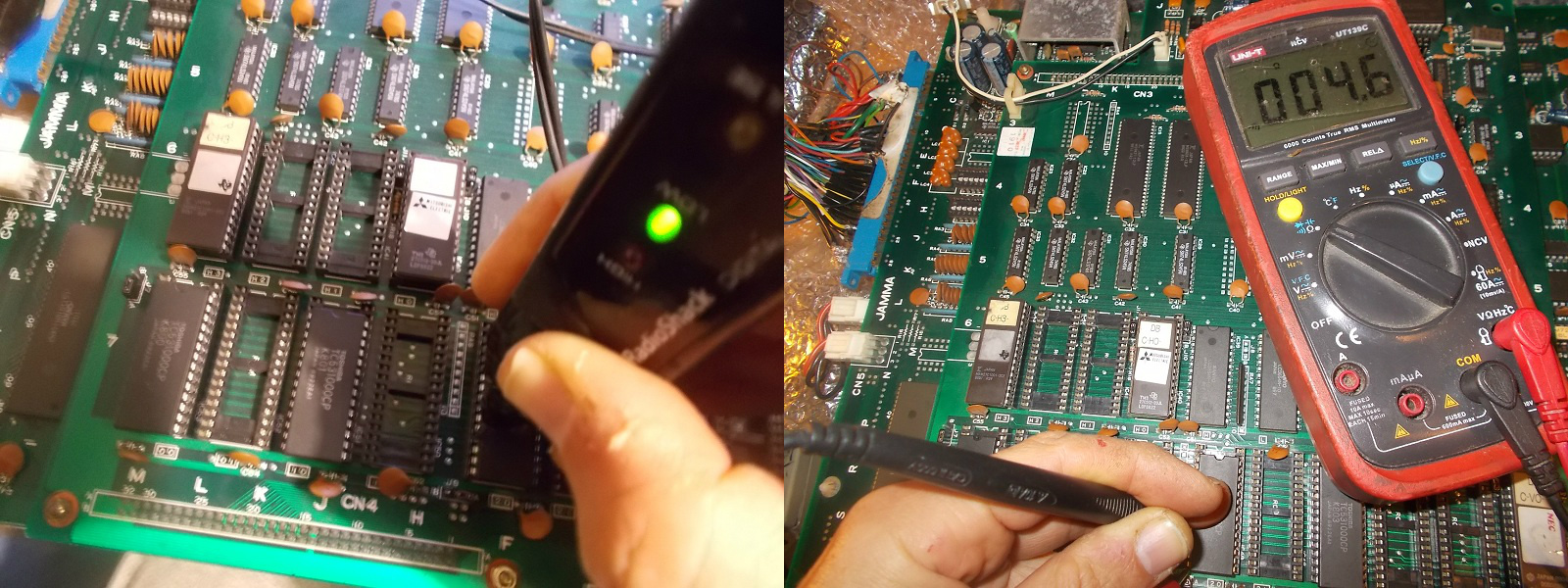
Due the fragile nature of these devices I was pretty sure that there was a faulty one but I was wrong since dumps turned out to be good.Analysing them with a logic probe I noticed that data line D0 (pin 11) of the MASK ROM @IC49 was stuck low, measuring its resistance to GND gave me only few Ohms:

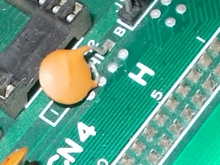
Since device was good there was clearly something forcing the pin low, most likely a short (not ‘dead’ though).I traced the involved pin back until I came across to this scenario:

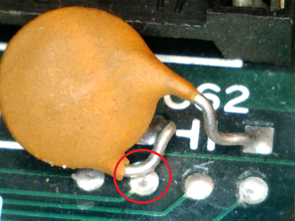
Here’s a close-up under a microscope:

The capacitor @C62 was bended and its terminal connected to GROUND  was accidentally lented on the pad of the trace tied to the data line.I straightened the capacitor, this cleared the short and hence sprites issue, simple but effective!Job done.


 Posted by at 7:29 pm

Rolling Thunder repair log #3

 PCB Repair Logs  Comments Off on Rolling Thunder repair log #3
Dec 242017
 

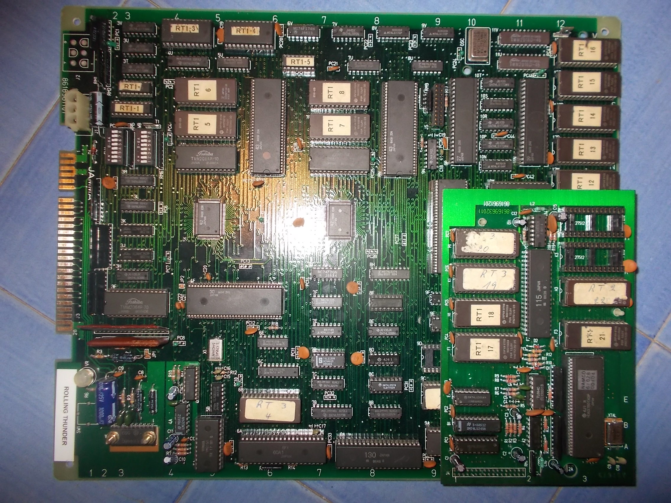
Received from Spain this faulty Rolling Thunder PCB for repair:

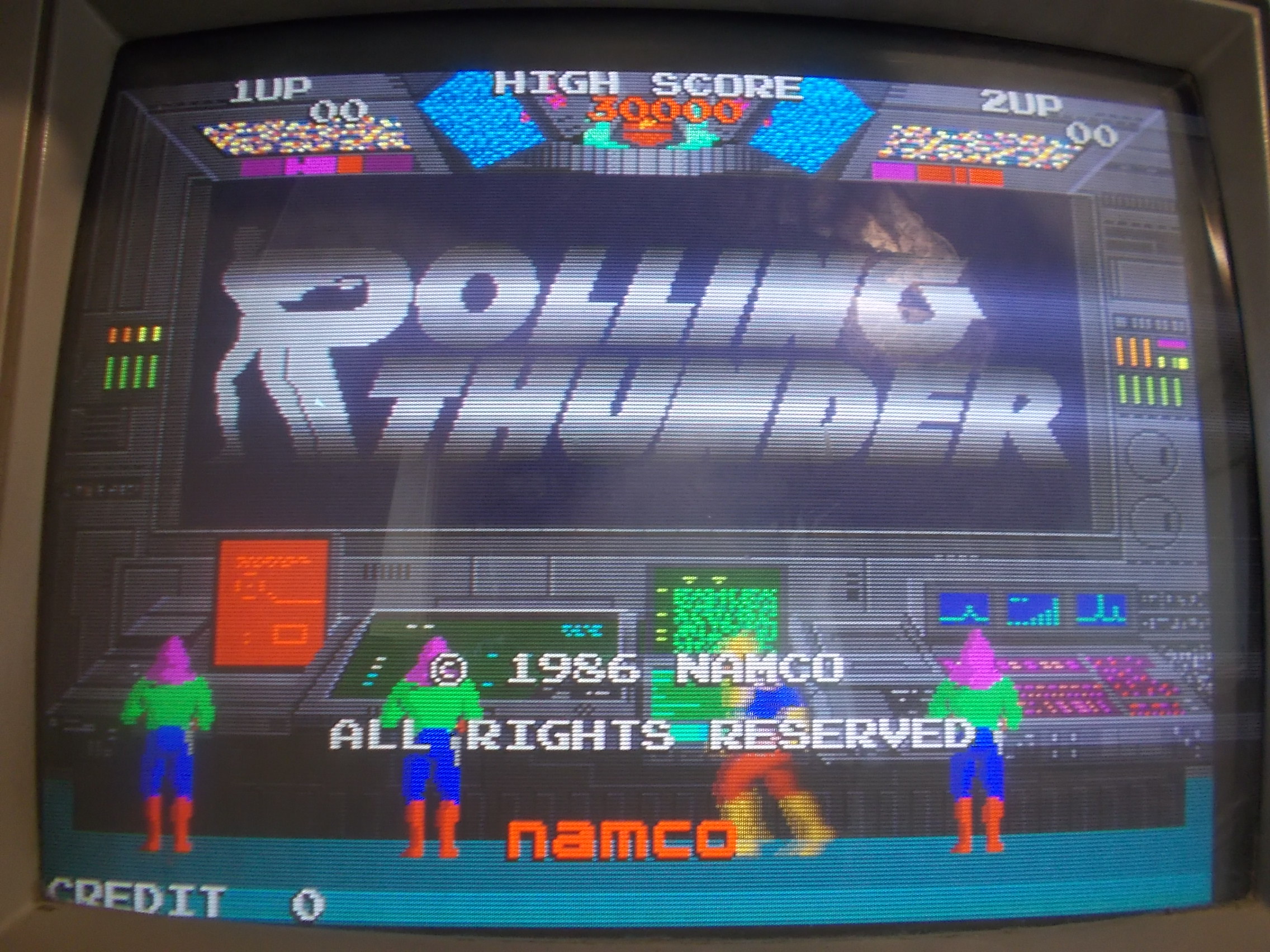
Board was not booting stuck on a static garbabe screen with some background sound noise (which seems a common issue on this PCB)

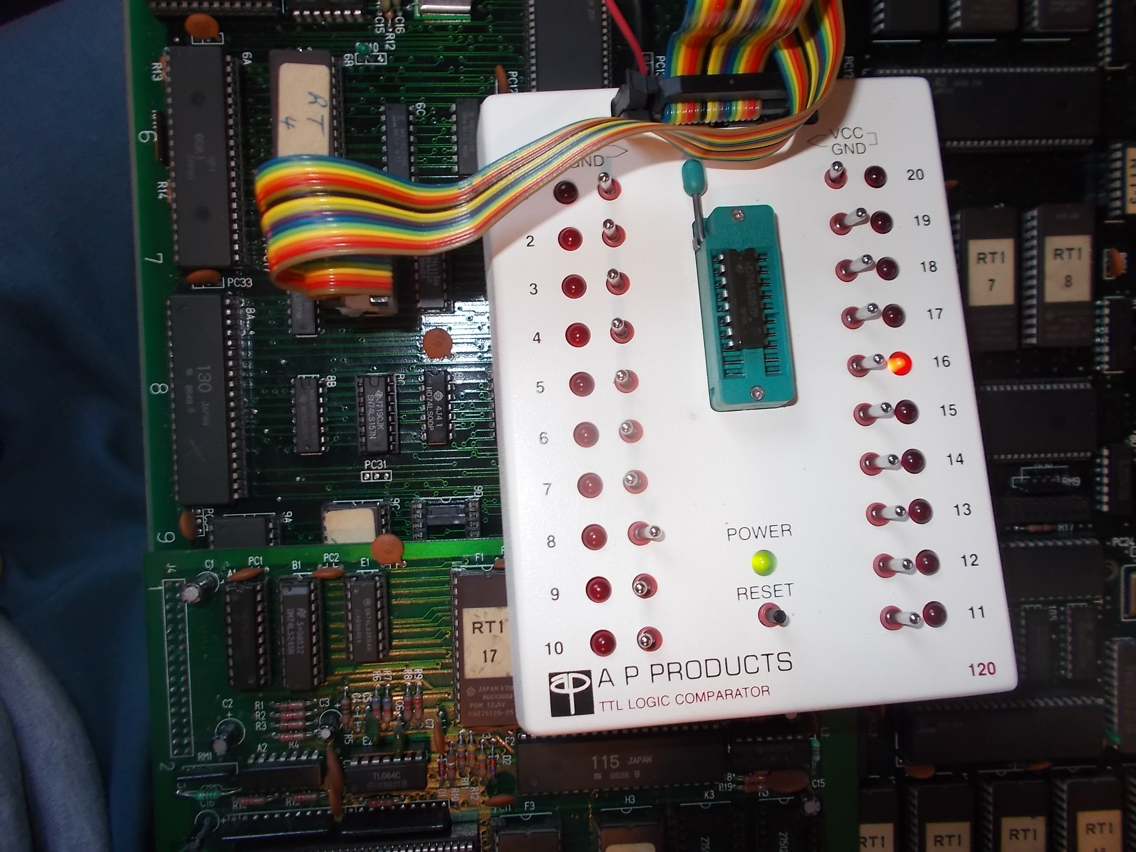
After ruled out all the custom ICs, few was left to test.The background sound noise very likely  suggested a problem in the digital sound circuit that on this hardware must be working for proper operation of the whole system.Probing this circuit with a logic comparator revealed nothing abnormal until I tested a 74LS257 @7C, I was warned about a problem on its output pin 12:


Also comparing with a scope this ouput with the one of the reference IC gave discrepancies, signal was not properly toggling (good on left of the below picture)

Looking at schematics pin 12 of this 74LS257 outputs the address line ‘A0′ to a 6264 static RAM @3F tied to the custom ’30’ which controls the sound system:

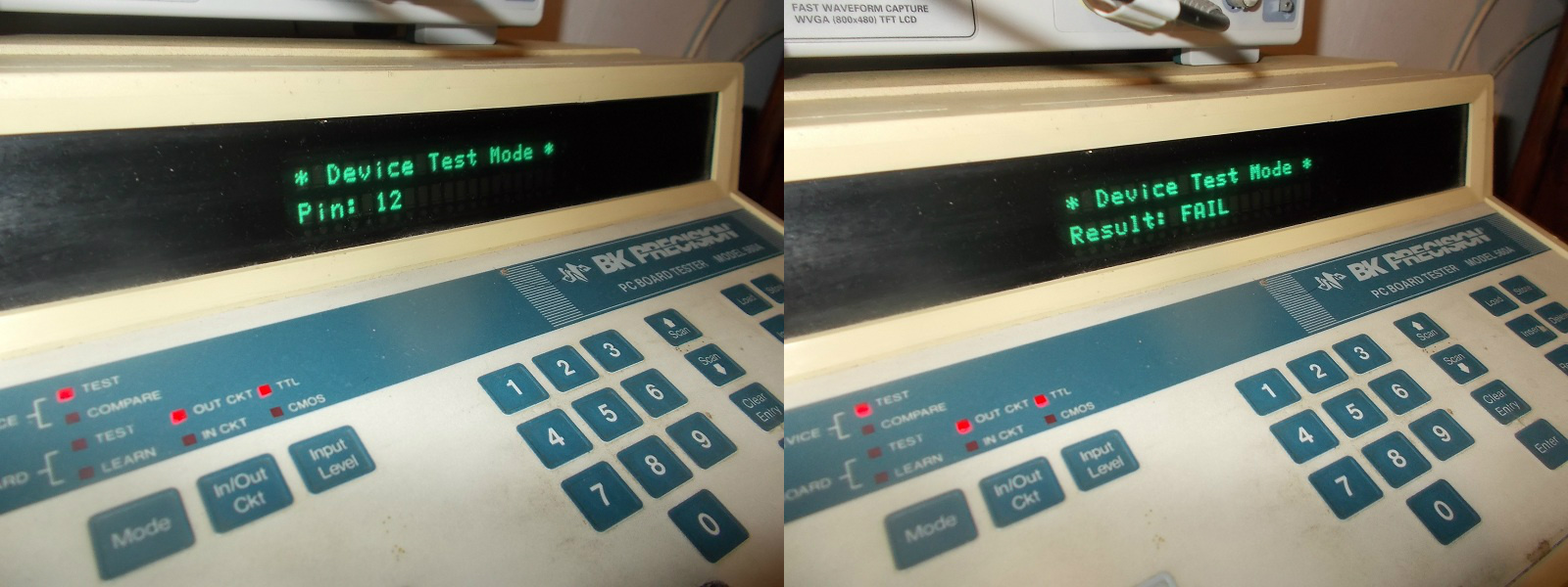
Sure enough I removed the TTL which failed the out-of-circuit exactly in pin 12:

After replaced the TTL the board successfully booted, no further issue were found so 100% fixed.


 Posted by at 4:23 pm

Dogyuun repair log #1

 PCB Repair Logs  Comments Off on Dogyuun repair log #1
Dec 192017
 

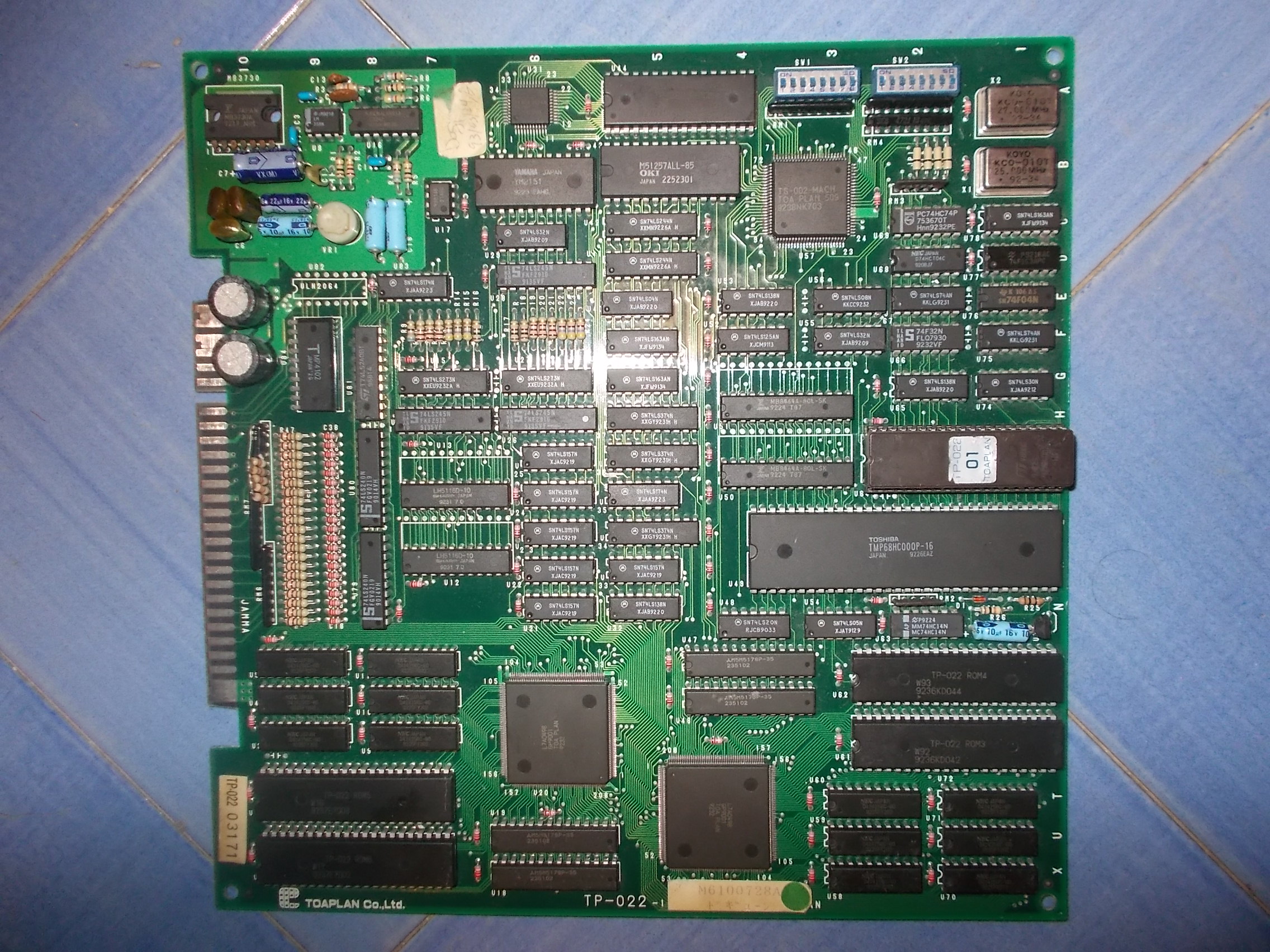
Got from Portugal this almost mint but not working Dogyuun PCB, a shoot ’em up released by Toaplan in 1992:

On power up, after the system got initialized, board sat on a black screen.Main 68000 CPU was halted at this point,no sign of activity on all busses and control lines:

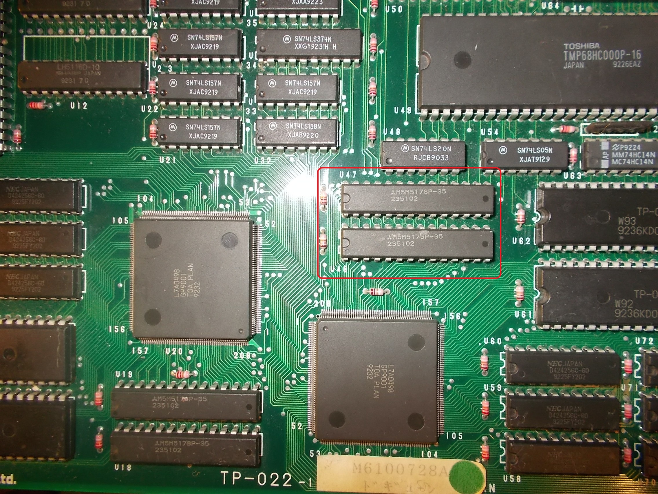
Usually this happens when a device (most of times RAMs) in the CPU address space doesn’t answer to initial check.So I went to probe RAMs and found that the two Mitsubishi M5M5178 @U46-U47 (8k x 8bit static RAM compatible with 6264) had /OE and /WE lines stuck (they are addessed by one of the GP9001 ASIC so the are VIDEO RAMs) 

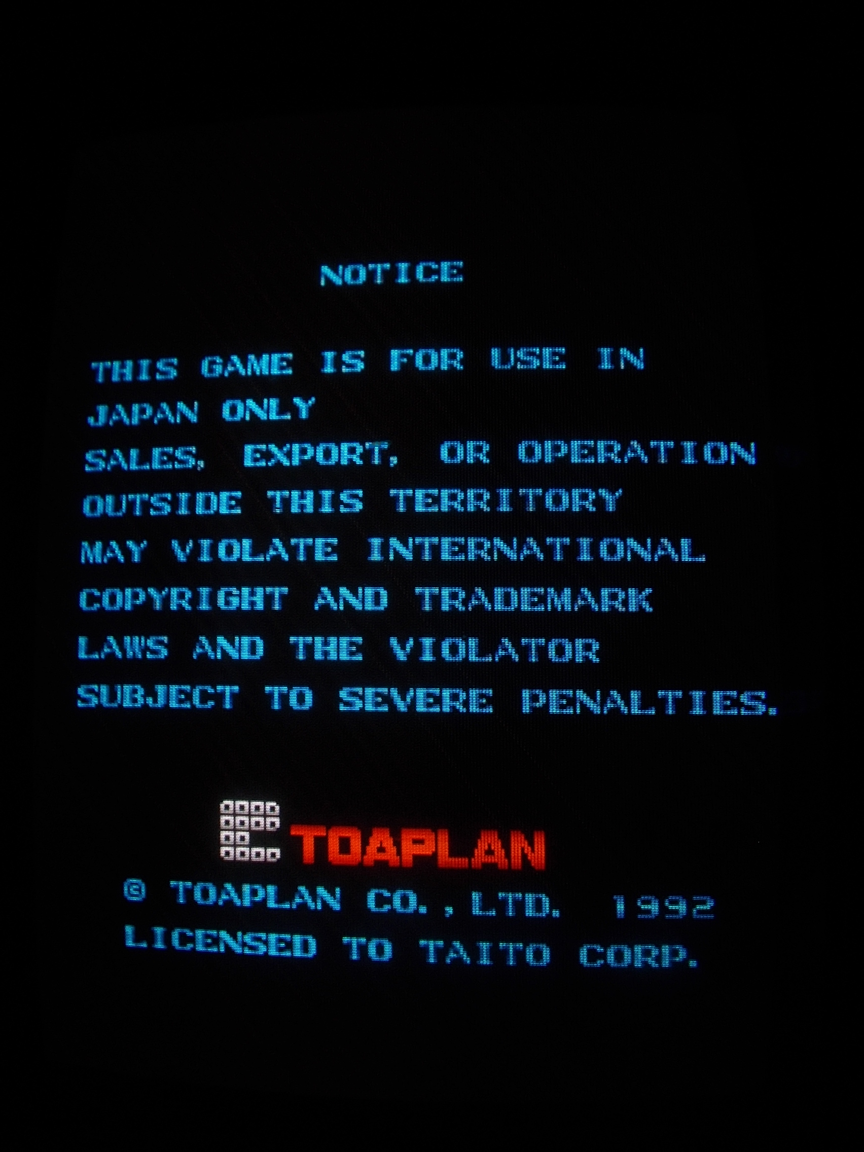
When I went to piggyback the one @U47 the board successfully booted and entered in game:

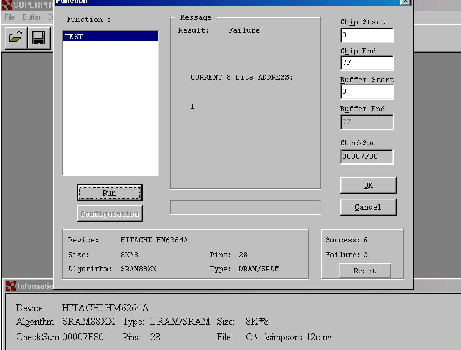
The chip obvioulsy failed the out-of-circuit test:

The game was fully playable but while testing I noticed some of the player 2 inputs didn’t work, in particular LEFT RIGHT, BUTTON 1 and 2 were responding at same time when one of them was activated.This can be clearly seen in the input check of TEST mode:

Checking with a logic probe the relevant pins of the  JAMMA edge connector revealed that they were floating when usually they must stay in HIGH state when not activated (and then LOW when input is activated).Pull-up resitors or resistors array are used most of times to keep the inputs in HIGH state.When I went to check with a multimeter the 4.7K array @RM7 I found no reading from pin 5 onwards :

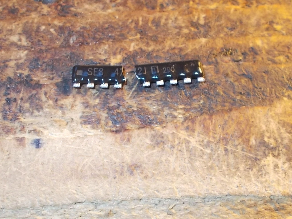
So it was most likely internally cracked.Indeed, once removed, it fell off in two parts:

Fitting a good one cured the issue.Board 100% fixed.


 Posted by at 5:01 pm